Magnetic resonance imaging (MRI) apparatus and manufacturing method thereof

a magnetic resonance imaging and magnetic resonance technology, applied in the direction of magnetic variable regulation, process and machine control, instruments, etc., can solve the problems of excessive space and degradation of image quality, and achieve the effect of preventing degradation of image quality and removing artifacts of eddy current through image postprocessing

Active Publication Date: 2016-11-01
SAMSUNG ELECTRONICS CO LTD
View PDF3 Cites 1 Cited by
  • Summary
  • Abstract
  • Description
  • Claims
  • Application Information

AI Technical Summary

Benefits of technology

[0013]Therefore, an aspect of the present invention provides a magnetic resonance imaging (MRI) apparatus in which conductors are installed in the space between a static coil unit and a gradient coil unit to eliminate asymmetry of eddy current induced in the static coil unit, so that the eddy current has a symmetrical distribution, and a manufacturing method of the MRI apparatus.
[0017]The one or more conductors can be installed in an excessive space that is made when the gradient coil unit deviates from a reference state in which the gradient coil unit forms a concentric body with the static coil unit, thereby adjusting the magnitude of eddy current induced in a portion of the static coil unit, the portion corresponding to the excessive space.
[0023]The one or more conductors can be installed in an area of the static coil unit in which a measured magnitude of eddy current is smaller than a magnitude of eddy current measured at another area of the static coil unit, and the smaller magnitude of the eddy current measured in the area or the larger size of the area results in the larger size of the one or more conductors that are installed in the area or in a larger quantity of the conductors.
[0033]The determining of the at least one of the size and number of the conductors may include increasing the size or number of the conductors that are installed in the installation location, as a smaller magnitude of eddy current is measured in the installation location of the conductors is determined based on the result of the measurement, or as the installation location is determined to be a larger area.
[0035]According to an exemplary aspect of the present invention, by installing conductors in areas from which a small magnitude of eddy current is measured to increase the eddy current in the areas, asymmetry of an eddy current distribution, generated due to surface treatment errors of a static coil unit or setup errors of the static coil unit and a gradient coil unit, can be eliminated so that the eddy current can be symmetrically distributed.
[0037]In addition, the present invention advantageously prevents degradation of image quality due to influence of eddy current.

Problems solved by technology

The eddy current induced in the static coil unit also induces a magnetic field that obstructs acquisition of normal images, resulting in degradation of image quality.
The installation location of the conductors can include an excessive space between the gradient coil unit and the static coil unit, the excessive space occurs when the gradient coil unit deviates from a reference state in which the gradient coil unit forms a concentric body with the static coil unit.

Method used


Image

  • Magnetic resonance imaging (MRI) apparatus and manufacturing method thereof
  • Magnetic resonance imaging (MRI) apparatus and manufacturing method thereof
  • Magnetic resonance imaging (MRI) apparatus and manufacturing method thereof

Examples


Embodiment Construction

[0055]Reference will now be made in detail to some of the exemplary embodiments of the present invention, examples of which are illustrated in the accompanying drawings, wherein like reference numerals refer to like elements throughout.

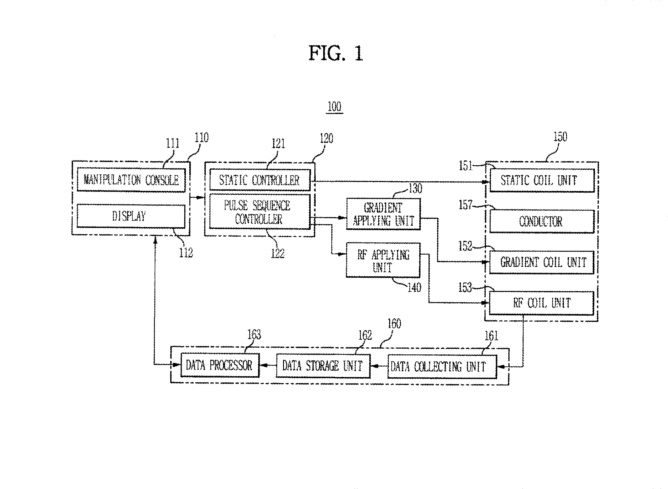
[0056]FIG. 1 is a control block diagram of a magnetic resonance imaging (MRI) apparatus 100 in accordance with an embodiment of the present invention;

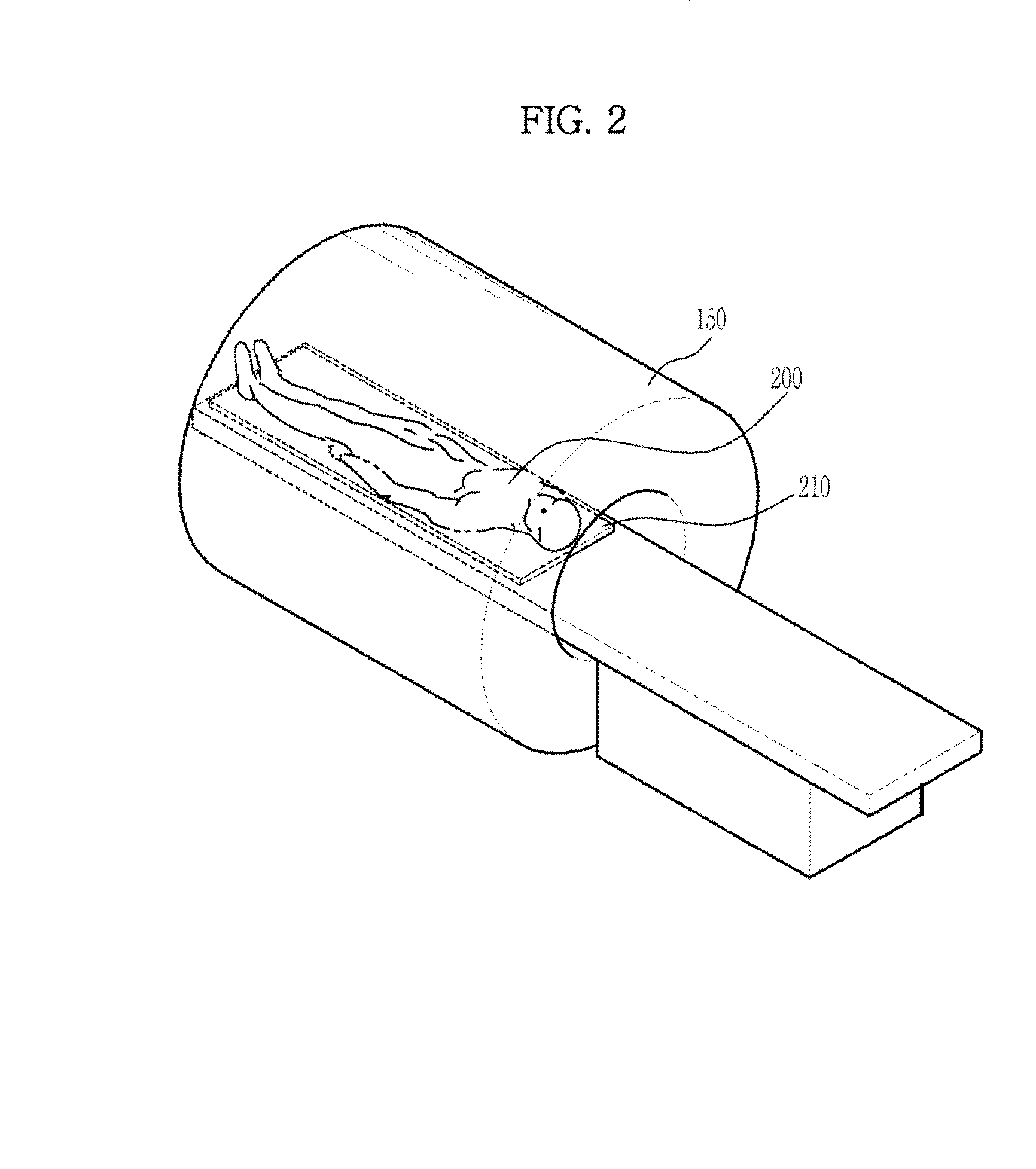
[0057]Referring now to FIG. 1, the MRI apparatus 100 in accordance with this exemplary embodiment of the present invention includes a magnet assembly 150 for forming a magnetic field to cause resonance in atomic nuclei, a controller 120 for controlling the operation of the magnet assembly 150, and an image processor 160 for receiving an echo signal generated from the atomic nuclei to create a magnetic resonance image.

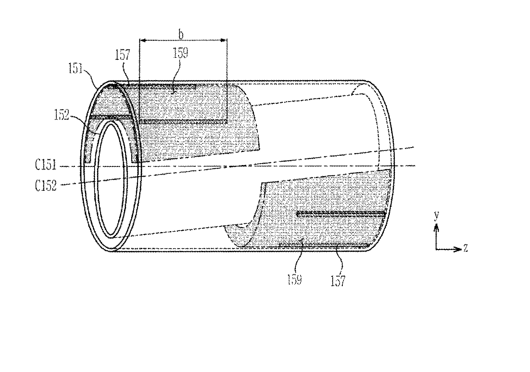
[0058]The magnet assembly 150 includes a static coil unit 151 for forming a static field thereinside, a gradient coil unit 152 for forming a gradient field in the static field, one or more c...


PUM

PropertyMeasurementUnit
magnetic fieldaaaaaaaaaa
precession frequencyaaaaaaaaaa
widthaaaaaaaaaa

Abstract

A magnetic resonance imaging (MRI) method and apparatus in which conductors are installed in the space between a static coil unit and a gradient coil unit to eliminate asymmetry of eddy current induced in the static coil unit. The structure permits a symmetrical distribution of eddy current when the concentric arrangement of the static coil unit and gradient coil unit has deviated. The MRI apparatus includes: a static coil unit configured to form a static field in a subject; a gradient coil unit configured to form a gradient field in the static field; and one or more conductors installed in the space between the static coil unit and the gradient coil unit, and configured to symmetrically distribute eddy current induced in the static coil unit.

Description

CLAIM OF PRIORITY[0001]This application claims the benefit of priority under 35 U.S.C. §119 from Korean Patent Application No. 10-2012-0105718, filed on Sep. 24, 2012 in the Korean Intellectual Property Office, the disclosure of which is incorporated herein by reference in its entirety.BACKGROUND[0002]1. Field of the Invention[0003]The present disclosure relates to a magnetic resonance imaging (MRI) apparatus for diagnosing various diseases using MRI, and a manufacturing method thereof.[0004]2. Description of the Related Art[0005]In general, a medical imaging system is an apparatus for providing imaging information about an internal area of a patient. The medical imaging system includes an X-ray machine, an ultrasonic diagnostic instrument, a computer tomography (CT) scanner, a magnetic resonance imaging (MRI) apparatus, etc.[0006]The MRI apparatus holds an important position in the field of medical imaging diagnosis because image-taking conditions are relatively free and the MRI ap...

Claims


Application Information

Patent Timeline
Patent Type & Authority Patents(United States)
IPC IPC(8): G01R33/385G01R33/00G01R33/38G01R33/381G01R33/28G01R33/565
CPCG01R33/28G01R33/0052G01R33/381G01R33/3802G01R33/3858G01R33/56518Y10T29/49004A61B5/055
Inventor CHOI, SEUNG JEPARK, DONG KEUNHWANG, GYU WAN
Owner SAMSUNG ELECTRONICS CO LTD
Why Eureka
Try Eureka