Heat Dissipating Fan

a technology of heat dissipation fan and fan body, which is applied in the direction of positive displacement liquid engine, piston pump, liquid fuel engine, etc., can solve the problems of adversely affecting the heat dissipation effect, dust is liable to accumulate inside the housing, air input and/or air output, etc., and achieve the effect of automatically removing dus

Active Publication Date: 2011-04-28
SUNONWEALTH ELECTRIC MACHINE IND
View PDF13 Cites 36 Cited by
  • Summary
  • Abstract
  • Description
  • Claims
  • Application Information

AI Technical Summary

Benefits of technology

[0006]An objective of the present invention is to provide

Problems solved by technology

However, dust carried by the air currents is liable to accumulate inside the housing at the air inlet, the air outlet, the blades of the impeller, etc., adversely affecting the

Method used


Image

  • Heat Dissipating Fan
  • Heat Dissipating Fan
  • Heat Dissipating Fan

Examples


first embodiment

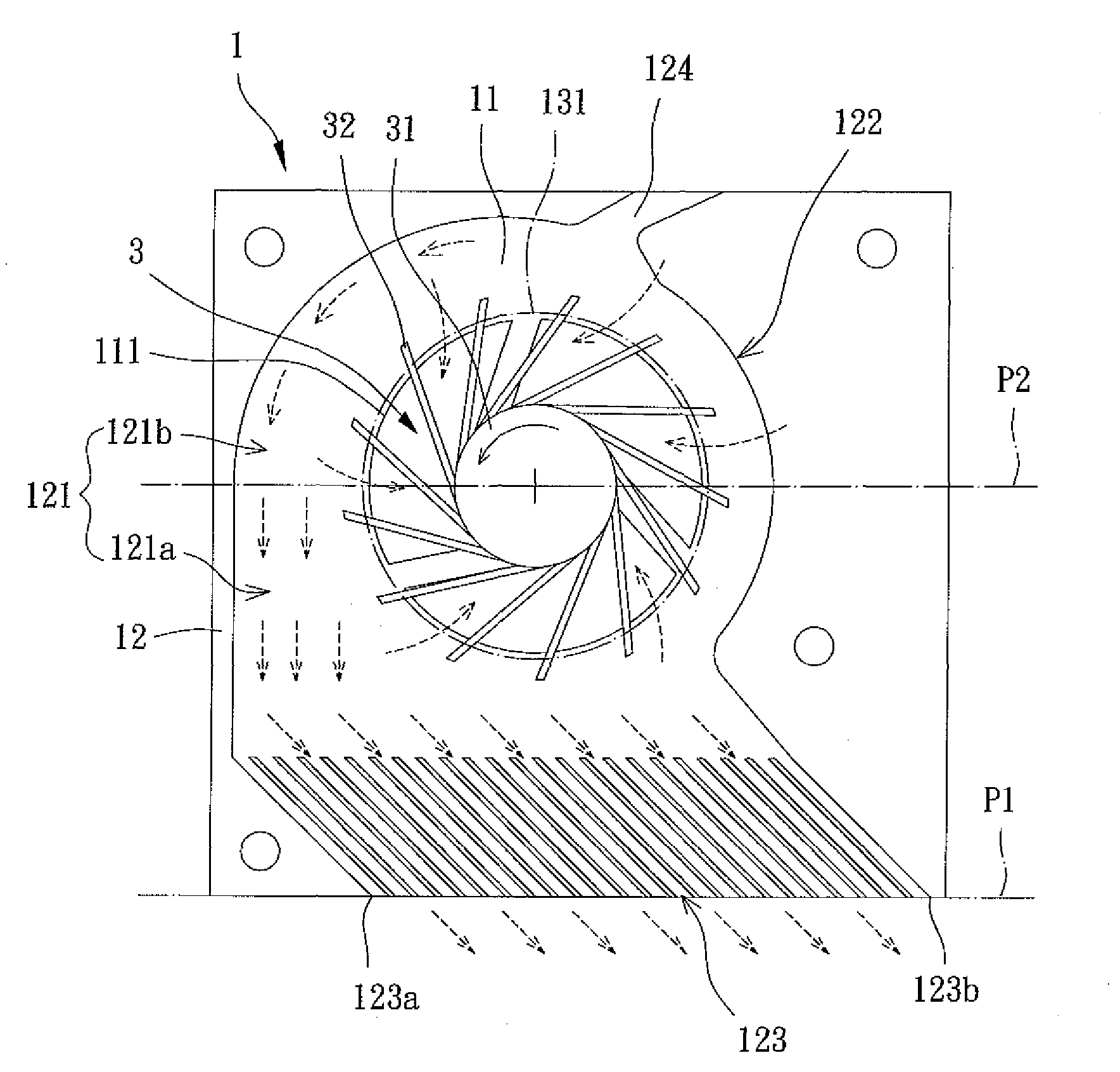
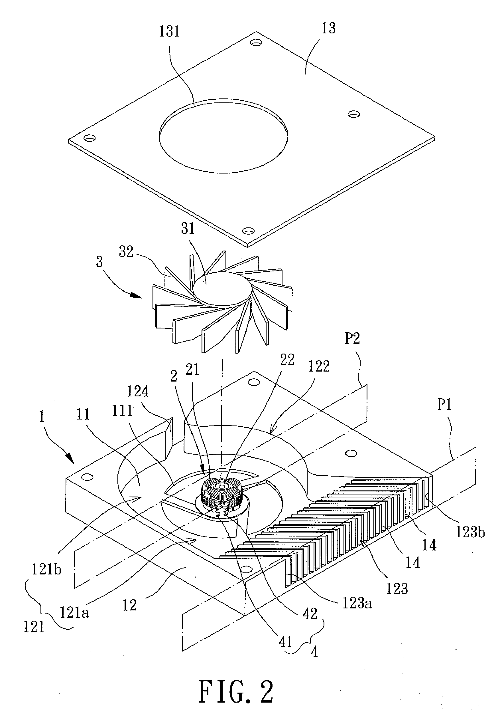
[0022]With reference to FIGS. 2 and 3, a heat dissipating fan of a first embodiment according to the preferred teachings of the present invention generally includes a housing 1, a stator 2, an impeller 3, and a control element 4. The housing 1 can be mounted in a desired location of an electronic product, such as a face of a main board inside a computer. The stator 2 is mounted in the housing 1. The impeller 3 is mounted in the housing 1 and rotatably coupled to the stator 2. The control element 4 controls the impeller 3 to rotate in a direction for generating enough amount of air for heat dissipating purposes or to rotate in a reverse direction for dust removing purposes by cooperating with the structure of the housing 1.

[0023]Specifically, the housing 1 includes a base 11 and a sidewall 12 coupled to a side of the base 11 and defining a compartment 121. The sidewall 12 includes an air inlet 122 and an air outlet 123 both in communication with the compartment 121. The sidewall 12 f...

second embodiment

[0037]FIGS. 6-8 show a heat dissipating fan of a second embodiment according to the preferred teachings of the present invention. In this embodiment, the heat dissipating fan includes a housing 5, a stator 6, an impeller 7, and a control element 8. Although the housing 5 is preferably of blower type, the housing 5 can be of axial-flow type. The stator 6 is mounted in the housing 5. The impeller 7 is rotatably coupled to the stator 6. The control element 8 controls the impeller 7 to rotate in the clockwise or counterclockwise direction.

[0038]Specifically, the housing 5 includes a base 51 and a lateral wall 52. The base 51 and the lateral wall 52 together define a compartment 521. The lateral wall 52 includes an air inlet 522 and an air outlet 523 both in communication with the compartment 521. The air inlet 522 can act as a dust channel.

[0039]The stator 6 is mounted to the base 51 of the housing 5 and includes a coil unit 61 and a shaft seat 62. The coil unit 61 is mounted around or ...


PUM


Abstract

A heat dissipating fan includes a housing having a base and a sidewall coupled to the base. The sidewall defines a compartment. The housing further includes an air inlet, an air outlet, and a dust channel. The air inlet, the air outlet, and the dust channel are in communication with the compartment. A stator is coupled to the base of the housing. An impeller is rotatably coupled to the stator. A control element includes a driving circuit electrically connected to the stator and a rotating direction control circuit electrically connected to the driving circuit. In another embodiment, the heat dissipating fan includes a housing having a base and a lateral wall coupled to the base. The lateral wall defines a compartment. The lateral wall includes an air inlet and an air outlet both in communication with the compartment. The air inlet also acts as a dust channel.

Description

BACKGROUND OF THE INVENTION[0001]1. Field of the Invention[0002]The present invention relates to a heat dissipating fan and, more particularly, to a heat dissipating fan with automatic dust removing function.[0003]2. Description of the Related Art[0004]Conventional heat dissipating fans generally include a housing having an air inlet and an air outlet. An impeller is rotatably mounted in the housing and driven by a driving unit also mounted in the housing to draw in ambient air via the air inlet. The air currents drawn into the housing are concentrated before exiting the air outlet to a heat source in an electronic product. The temperature of the heat source during operation is, thus, lowered. However, dust carried by the air currents is liable to accumulate inside the housing at the air inlet, the air outlet, the blades of the impeller, etc., adversely affecting the air input and / or air output and, thus, adversely affecting the heat dissipating effect.[0005]FIG. 1 shows a heat diss...

Claims


Application Information

Patent Timeline
IPC IPC(8): F04D29/70F04D29/42
CPCF04D27/004F04D29/701F04D29/4226Y02B30/70
Inventor HORNG, ALEXLEE, CHAO-HSUNWANG, CHI-MIN
Owner SUNONWEALTH ELECTRIC MACHINE IND
Why Eureka
Try Eureka