Cooling fan and housing thereof

a cooling fan and housing technology, applied in the direction of positive displacement liquid engines, piston pumps, liquid fuel engines, etc., can solve the problems of air input and/or air output, adversely affecting the heat dissipation effect, dust is liable to accumulate inside the housing, etc., and achieve the effect of automatically removing dus

Active Publication Date: 2014-04-22
SUNONWEALTH ELECTRIC MACHINE IND
View PDF21 Cites 8 Cited by
  • Summary
  • Abstract
  • Description
  • Claims
  • Application Information

AI Technical Summary

Benefits of technology

[0007]Another objective of the present invention is to provide a cooling fan with reliable input and output of air by automatically removing dust.
[0009]Still another objective of the present invention is to provide a housing for a cooling fan to prevent the dust to be removed from flowing back into an interior of the housing.

Problems solved by technology

However, dust carried by the air currents is liable to accumulate inside the housing at the air inlet, the air outlet, the blades of the impeller, etc., adversely affecting the air input and / or air output and, thus, adversely affecting the heat dissipating effect.
However, dust is liable to accumulate inside the housing 91 after a period of time of use.

Method used


Image

  • Cooling fan and housing thereof
  • Cooling fan and housing thereof
  • Cooling fan and housing thereof

Examples


Embodiment Construction

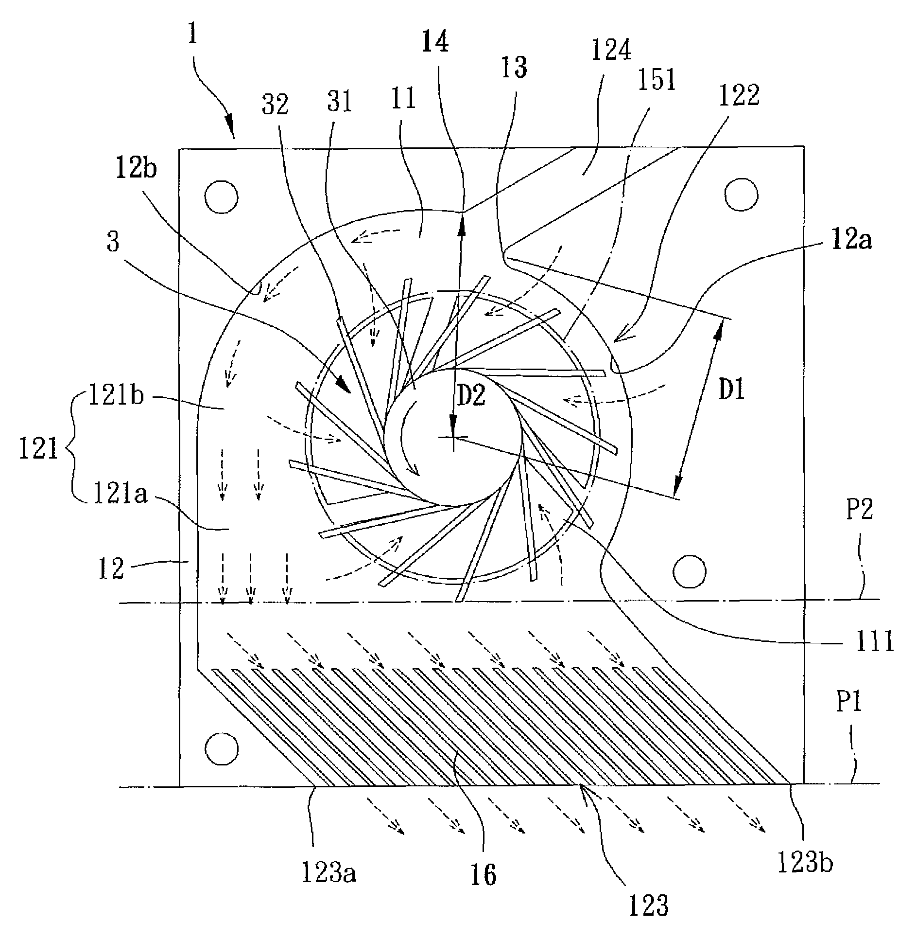
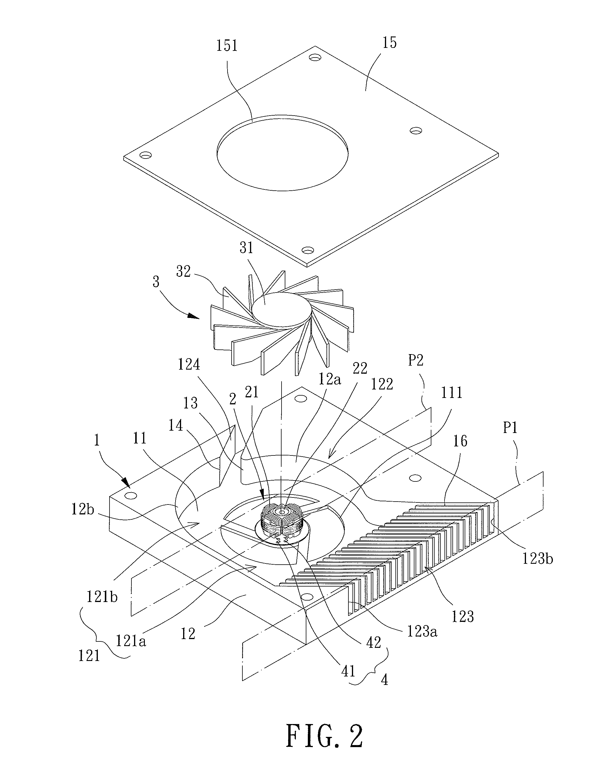
[0023]With reference to FIG. 2, a cooling fan of an embodiment according to the present invention generally includes a housing 1, a stator 2, an impeller 3, and a control element 4. The housing 1 can be mounted in a desired location of an electronic product, such as a face of a main board inside a computer. The stator 2 is mounted in the housing 1. The impeller 3 is mounted in the housing 1 and rotatably coupled to the stator 2. The control element 4 controls the impeller 3 to rotate in a first direction for generating a sufficient amount of air for cooling purposes or to rotate in a reverse, second direction for dust removing purposes by cooperating with the structure of the housing 1.

[0024]Specifically, the housing 1 includes a base 11 and a sidewall 12 coupled to a side of the base 11 and defining a compartment 121. The sidewall 12 includes an air inlet 122 and an air outlet 123 both in communication with the compartment 121. The sidewall 12 further includes a dust channel 124 in...


PUM


Abstract

A cooling fan includes a sidewall coupled to a base of a housing and defining a compartment. The housing includes an air inlet, an air outlet, and a dust channel. The air inlet, the air outlet, and the dust channel are in communication with the compartment. An impeller is rotatably coupled to a stator coupled to the base. A control element includes a driving circuit electrically connected to the stator and a rotating direction control circuit electrically connected to the driving circuit. The air outlet and the dust channel separate an inner periphery of the sidewall into first and second guiding wall sections. The first guiding wall section has a guiding portion contiguous to the dust channel. A first spacing between the guiding portion and a center of the impeller is not larger than a second spacing between the second guiding wall section and the center of the impeller.

Description

BACKGROUND OF THE INVENTION[0001]1. Field of the Invention[0002]The present invention relates to a cooling fan and a housing thereof and, more particularly, to a cooling fan with an automatic dust removing function and a housing thereof.[0003]2. Description of the Related Art[0004]Conventional cooling fans generally include a housing having an air inlet and an air outlet. An impeller is rotatably mounted in the housing and driven by a driving unit also mounted in the housing to draw in ambient air via the air inlet. The air currents drawn into the housing are concentrated before exiting the air outlet to a heat source in an electronic product. The temperature of the heat source during operation is, thus, lowered. However, dust carried by the air currents is liable to accumulate inside the housing at the air inlet, the air outlet, the blades of the impeller, etc., adversely affecting the air input and / or air output and, thus, adversely affecting the heat dissipating effect.[0005]FIG....

Claims


Application Information

Patent Timeline
Patent Type & Authority Patents(United States)
IPC IPC(8): F04B35/04
CPCF04D25/0633F04D29/701F04D29/4226
Inventor HORNG, ALEX
Owner SUNONWEALTH ELECTRIC MACHINE IND
Why Eureka
Try Eureka