Eureka AIR delivers breakthrough ideas for toughest innovation challenges, trusted by R&D personnel around the world.

Locking assembly and electronic enclosure using same

Inactive Publication Date: 2011-05-19
HONG FU JIN PRECISION IND (SHENZHEN) CO LTD +1
View PDF28 Cites 8 Cited by
  • Summary
  • Abstract
  • Description
  • Claims
  • Application Information

AI Technical Summary

Benefits of technology

[0005]Conventionally, a plurality of screws are applied to lock the cover onto the base. However, such means needs additional tools such as screwdrivers during assembly, which is time consuming and troublesome.

Problems solved by technology

However, such means needs additional tools such as screwdrivers during assembly, which is time consuming and troublesome.

Method used


Image

  • Locking assembly and electronic enclosure using same
  • Locking assembly and electronic enclosure using same
  • Locking assembly and electronic enclosure using same

Examples


Embodiment Construction

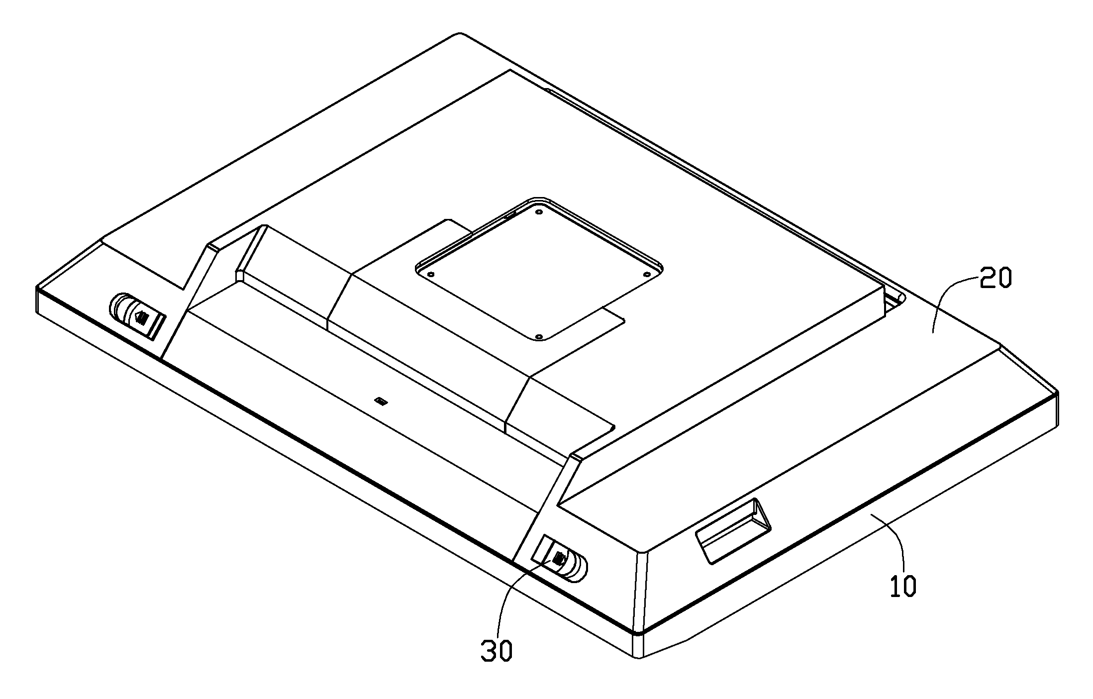
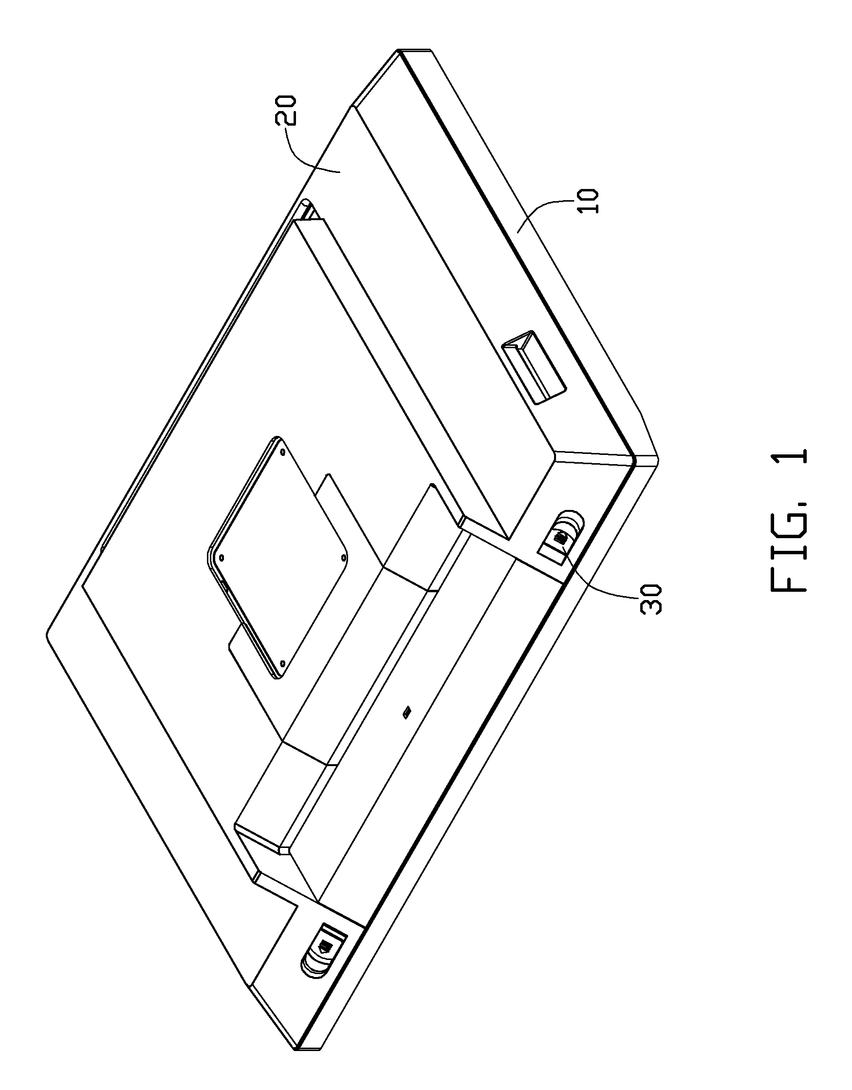
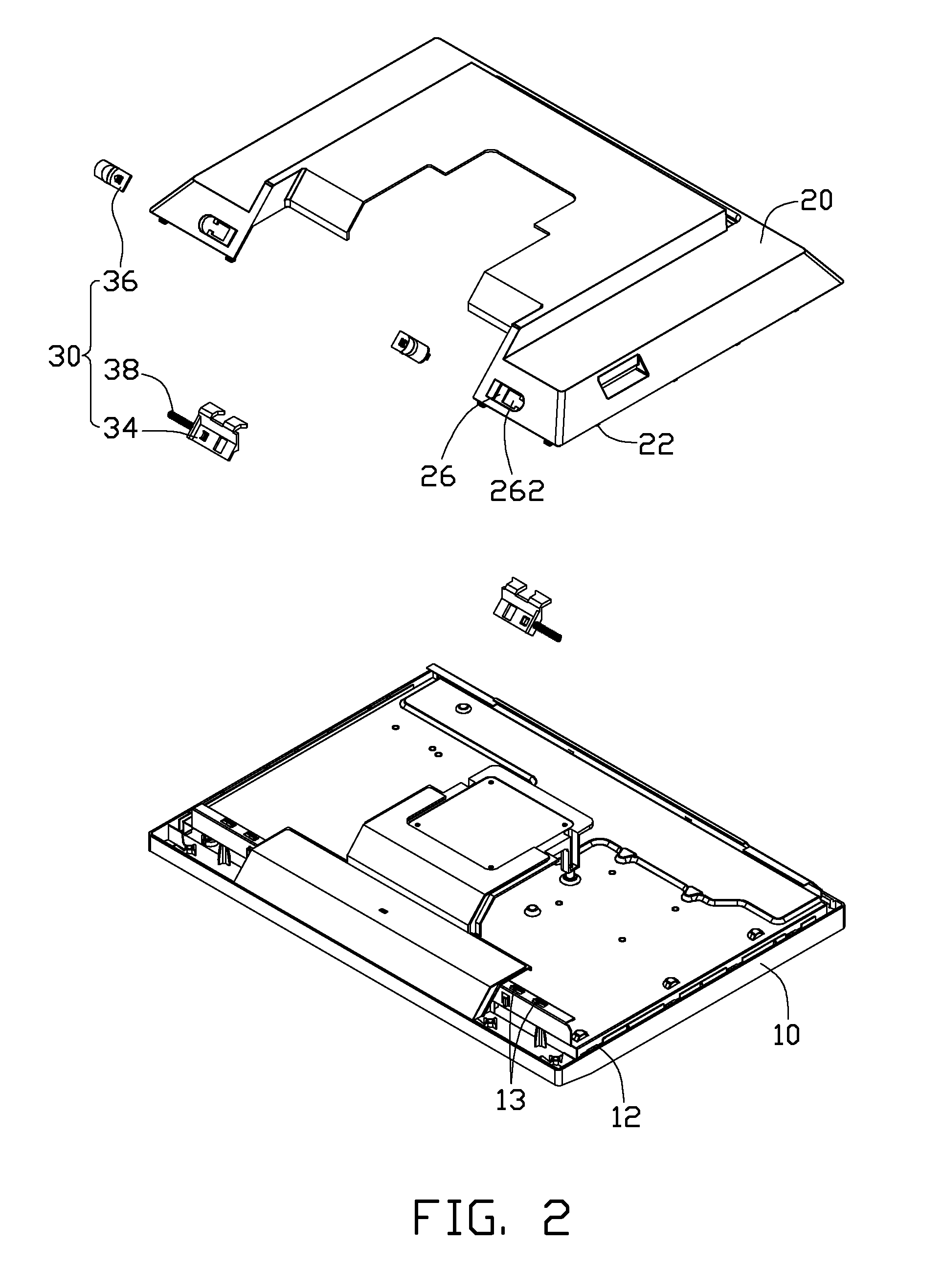
[0014]The locking assembly for an electronic enclosure in accordance with an exemplary embodiment of the present disclosure is applied to a monitor enclosure as an example. Understandably, the locking assembly can be used in computer housings or other enclosures of electronic devices.

[0015]Referring to FIGS. 1-3, and 6-7, the monitor enclosure comprises a base 10, a cover 20 mounted on the base 10, and two locking members 30 assembled on the cover 20. A plurality of supporting recesses 12 are defined in the base 10, and two supporting portions 13 are formed on the base 10. A plurality of barbs 22 are formed on the cover 20 to match with the supporting recesses 12. The locking members 30 each comprise a securing portion34 movably assembled on a bottom of the cover 20, an operating portion 36 mounted on a top of the cover 20 and extended through the cover 20 to connect to the securing portion 34, and a flexible member 38 abutting against both the securing portion 34 and the cover 20. ...


PUM


Abstract

An enclosure includes a base, a cover mounted on the base, and two locking members assembled on the cover. A plurality of supporting recesses and two supporting portions are defined in the base. A plurality of barbs are formed on the cover to match with the supporting recesses. The locking members each include a securing portion movably assembled on a bottom of the cover, an operating portion mounted on a top of the cover and extending through the cover and connected to the securing portion, and a flexible member abutting against both the securing portion and the cover. The securing portion is engaged with a corresponding supporting portion to secure the cover on the base. The securing portion can be operated to disengage from the supporting portion to remove the cover from the base.

Description

BACKGROUND[0001]1. Technical Field[0002]The present disclosure relates to a locking assembly, and particularly to a locking assembly for an electronic enclosure.[0003]2. Description of Related Art[0004]Usually, an enclosure of an electronic device such as a computer housing or a monitor, includes a base and a cover covering the base. Users can assemble electronic elements such as a main board onto the base and apply the cover to seal the enclosure, protecting the electronic elements.[0005]Conventionally, a plurality of screws are applied to lock the cover onto the base. However, such means needs additional tools such as screwdrivers during assembly, which is time consuming and troublesome.[0006]Therefore, there is room for improvement within the art.BRIEF DESCRIPTION OF THE DRAWINGS[0007]FIG. 1 is an isometric view of a locking assembly in accordance with an exemplary embodiment of the disclosure applied in a monitor enclosure.[0008]FIG. 2 is an exploded, isometric view of the monit...

Claims


Application Information

Patent Timeline
IPC IPC(8): A47B81/00E05C1/08E05C1/10H05K5/00
CPCG06F1/1679Y10T292/096Y10T292/0961Y10T292/0969Y10T292/097
Inventor XU, CHANG-ZHENGLIN, YANG-MINGCHEN, HSUAN-TSUNGLEE, GUANG-YAO
Owner HONG FU JIN PRECISION IND (SHENZHEN) CO LTD
Why Eureka
Eureka Blog
Learn More