In situ heating for reservoir chamber development

a technology for reservoir chambers and reservoirs, applied in the direction of fluid removal, earth-moving drilling, wellbore/well accessories, etc., can solve the problems of preventing the achievement of performance levels as high, affecting the development of reservoir chambers, and reducing the percentage of oil recovered from the area located between two adjacent steam chambers , to achieve the effect of facilitating lateral development of steam chambers

Active Publication Date: 2011-05-26
CONOCOPHILLIPS CO
View PDF5 Cites 32 Cited by
  • Summary
  • Abstract
  • Description
  • Claims
  • Application Information

AI Technical Summary

Benefits of technology

[0007]In one embodiment, a method of obtaining recovery from a reservoir includes supplying electric current to an auxiliary well offset in a lateral direction from a well pair arranged for steam assisted gravity drainage of oil in a formation. The method further includes injecting steam into the formation through an injector of the well pair and producing through a producer of the well pair both oil heated by the steam and water condensate to develop within the formation a steam chamber. Heating of the oil as a result of the electric current being supplied to the auxiliary well facilitates lateral development of the steam chamber.

Problems solved by technology

Cost of prior approaches to drain reservoirs containing the oil with a natural viscosity that inhibits the recovery makes any inefficiency a problem.
Various factors may prevent achieving performance levels as high as desired or needed for economic success.
As a result, percentage of the oil recoverable from areas located between two adjacent steam chambers and toward bottoms of the chambers diminishes relative to where the chambers form and may merge together in the formation.

Method used


Image

  • In situ heating for reservoir chamber development
  • In situ heating for reservoir chamber development
  • In situ heating for reservoir chamber development

Examples


Embodiment Construction

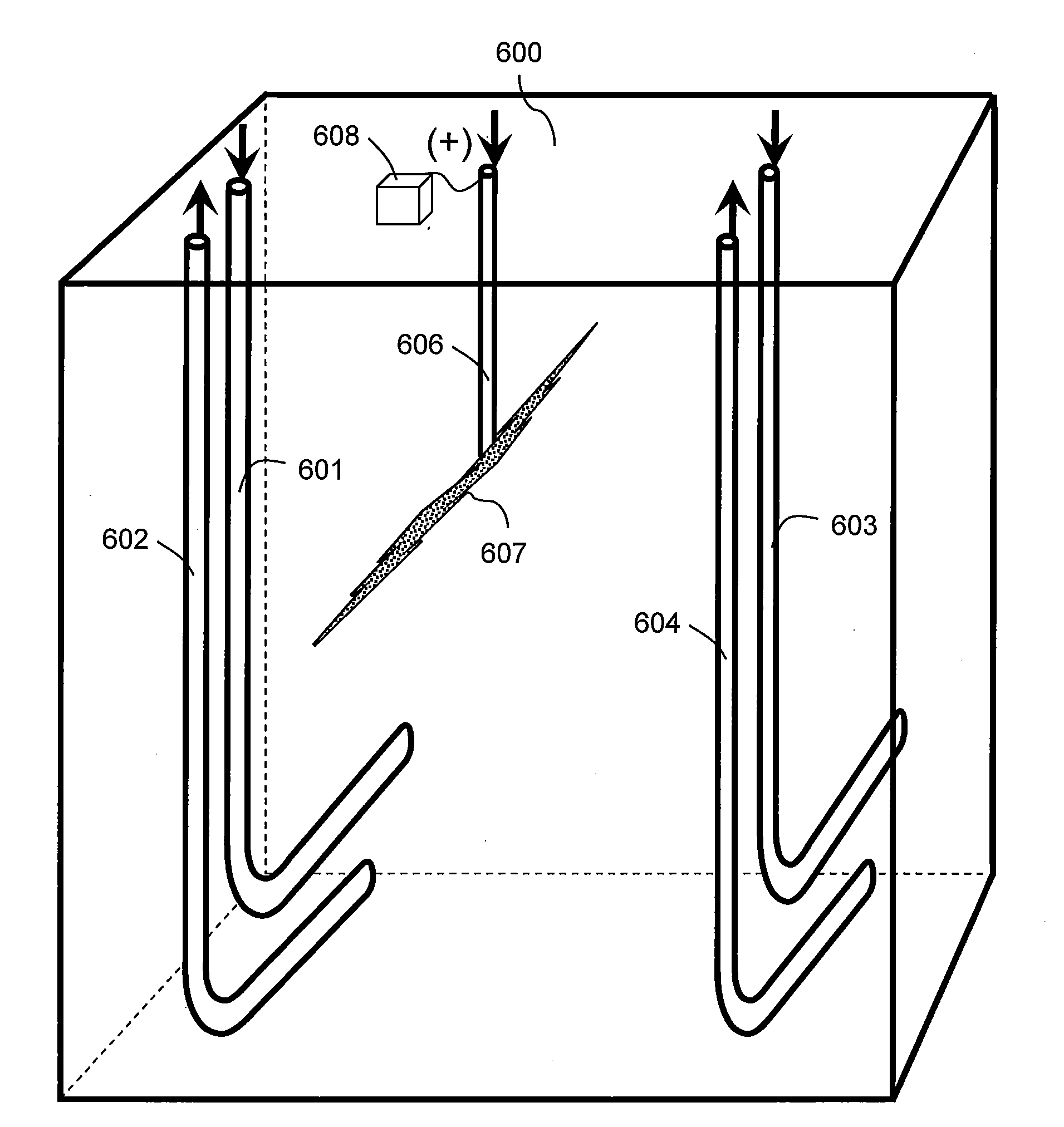
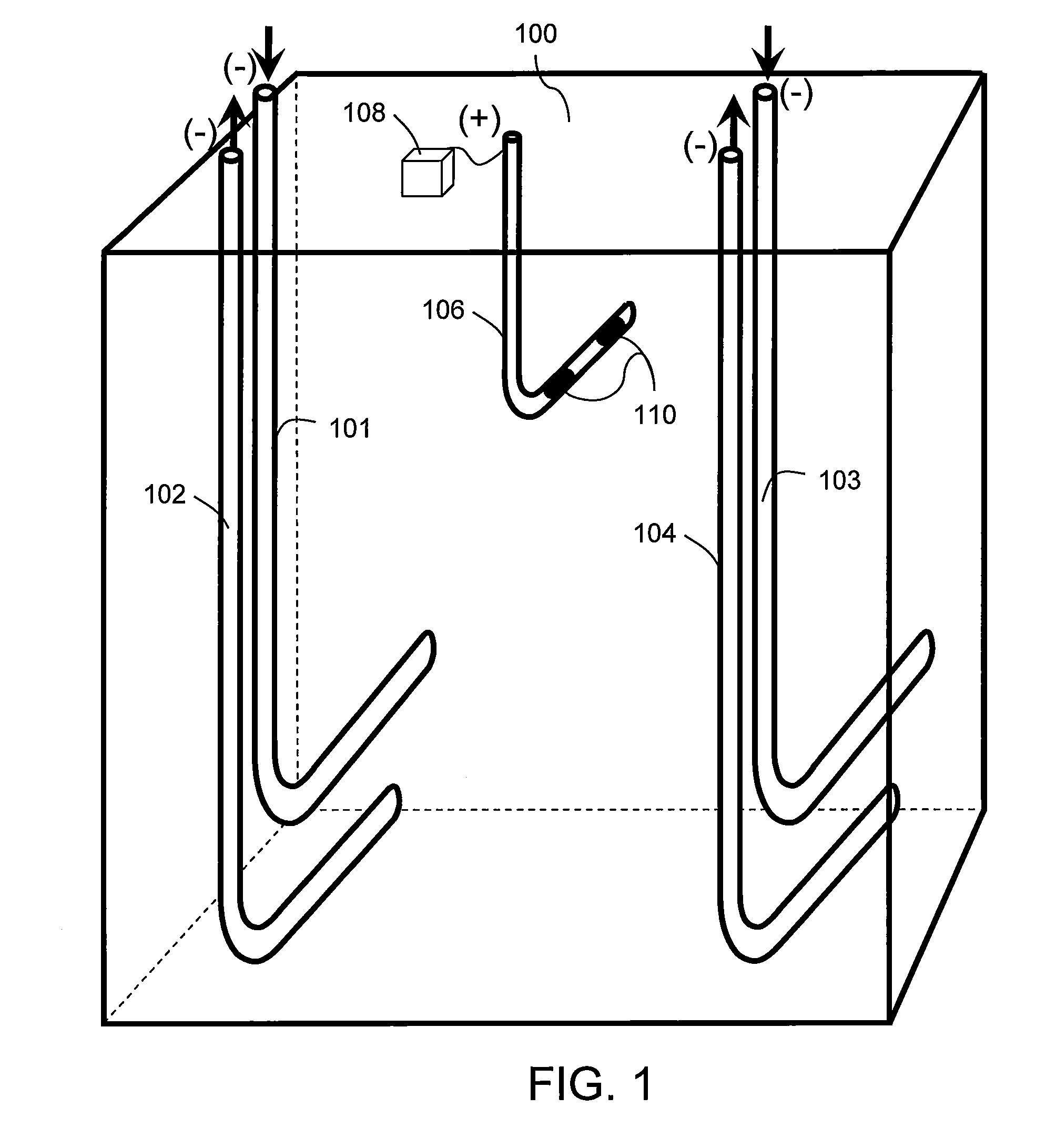
[0017]Embodiments of the invention relate to systems and methods to recover oil from a formation. In operation, a steam chamber develops as a result of steam injection into the formation and the recovery of fluids including the oil through a production well. An auxiliary well spaced in a lateral direction from the production well helps ensure development of the steam chamber as desired. The auxiliary well may enable heating of the formation through establishing an electric potential between the auxiliary well and the production well or by resistive heating of material forming the auxiliary well. Further, the auxiliary well may provide a flow path for solvent or gas injection to facilitate the recovery through the production well.

[0018]FIG. 1 illustrates a formation 100 that includes a first injector 101 arranged to pair with a first producer 102 and a second injector 103 paired with a second producer 104. Each of the injectors and producers 101-104 include horizontal borehole length...


PUM


Abstract

Methods and apparatus relate to systems and methods of recovering oil from a formation. In operation, a steam chamber develops as a result of steam injection into the formation and the recovery of fluids including the oil through a production well. An auxiliary well spaced in a lateral direction from the production well helps ensure development of the steam chamber as desired. The auxiliary well may enable heating of the formation through establishing an electric potential between the auxiliary well and the production well or by resistive heating of material forming the auxiliary well. Further, the auxiliary well may provide a flow path for solvent or gas injection to facilitate the recovery through the production well.

Description

CROSS-REFERENCE TO RELATED APPLICATIONS[0001]This application is a non-provisional application which claims benefit under 35 USC §119(e) to U.S. Provisional Application Ser. No. 61 / 263,547 filed Nov. 23, 2009, entitled “IN SITU HEATING FOR RESERVOIR CHAMBER DEVELOPMENT,” which is incorporated herein in its entirety.STATEMENT REGARDING FEDERALLY SPONSORED RESEARCH OR DEVELOPMENT[0002]NoneFIELD OF THE INVENTION[0003]Embodiments of the invention relate to methods and systems for in situ electric heating with steam assisted oil recovery.BACKGROUND OF THE INVENTION[0004]In order to recover oils from certain geologic formations, steam can be injected to increase the mobility of the oil within the formation via such processes known as steam assisted gravity drainage (SAGD). The oil that is made mobile enough to flow through the formation due to gravity gathers in a well for production. Cost of prior approaches to drain reservoirs containing the oil with a natural viscosity that inhibits th...

Claims


Application Information

Patent Timeline
Patent Type & Authority Applications(United States)
IPC IPC(8): E21B43/24
CPCE21B43/2408E21B43/2406
Inventor DONG, SHUXINGWHEELER, THOMAS J.DREHER, JR., W. REID
Owner CONOCOPHILLIPS CO
Why Eureka
Try Eureka