High definition video/audio data over IP networks

a video/audio data and high-definition technology, applied in the field of high-definition video/audio data over ip networks, can solve the problems of ip network, image quality limitations, variable delays, etc., and achieve the effect of cost-effectiveness

Inactive Publication Date: 2011-05-26
BAROX KOMMUNIKATION
View PDF16 Cites 23 Cited by
  • Summary
  • Abstract
  • Description
  • Claims
  • Application Information

AI Technical Summary

Benefits of technology

[0014]The present invention provides a solution for these and other problems by furnishing

Problems solved by technology

Though it would be very advantageous to use the IP for such transmissions, there are numerous problems connected with transmitting and synchronizing of HD video/audio data over an IP network or using the IP in a non-IP network.
If HD video/audio content is transmitted using the IP, other use of the IP network is limited because of the bandwidth needed: using H.264 (MPEG-4/AVC) introduces high latency and using JPEG or Motion JPEG results in image quality limitations.
However, when the packets traverse network adapters, switches, and other network nodes, they must be buffered and queued which results in variable delays, depending on the traffic load in the network.
This is one of the inherent problems of transmitting HD video/audio data over packet switching networks.
Obviously this is not an easy task and requires solving a number of problems when HD video/audio data are to be transmitted.
One of these problems is the synchronization of the audio with the video data.
This is a problem because, usually, the video data are transmitted separately from the audio data.
A second problem is the unavoid

Method used


Image

  • High definition video/audio data over IP networks
  • High definition video/audio data over IP networks
  • High definition video/audio data over IP networks

Examples


Embodiment Construction

[0047]Below, an embodiment of the invention with various modifications is described in conjunction with the drawings, as follows:

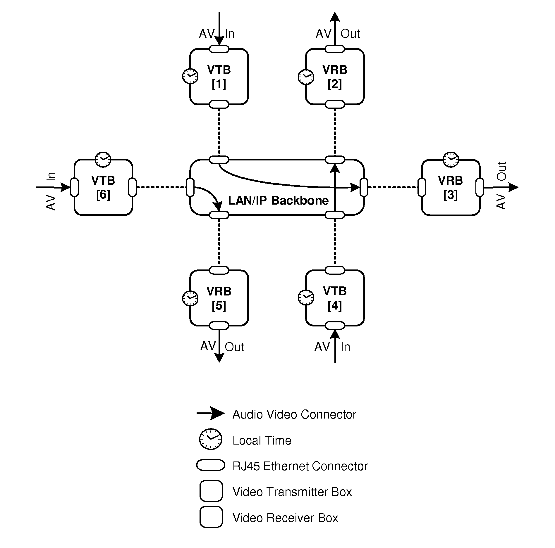
[0048]FIG. 1 a network with some video transmitter boxes (VTBs) and video receiver boxes (VRBs);

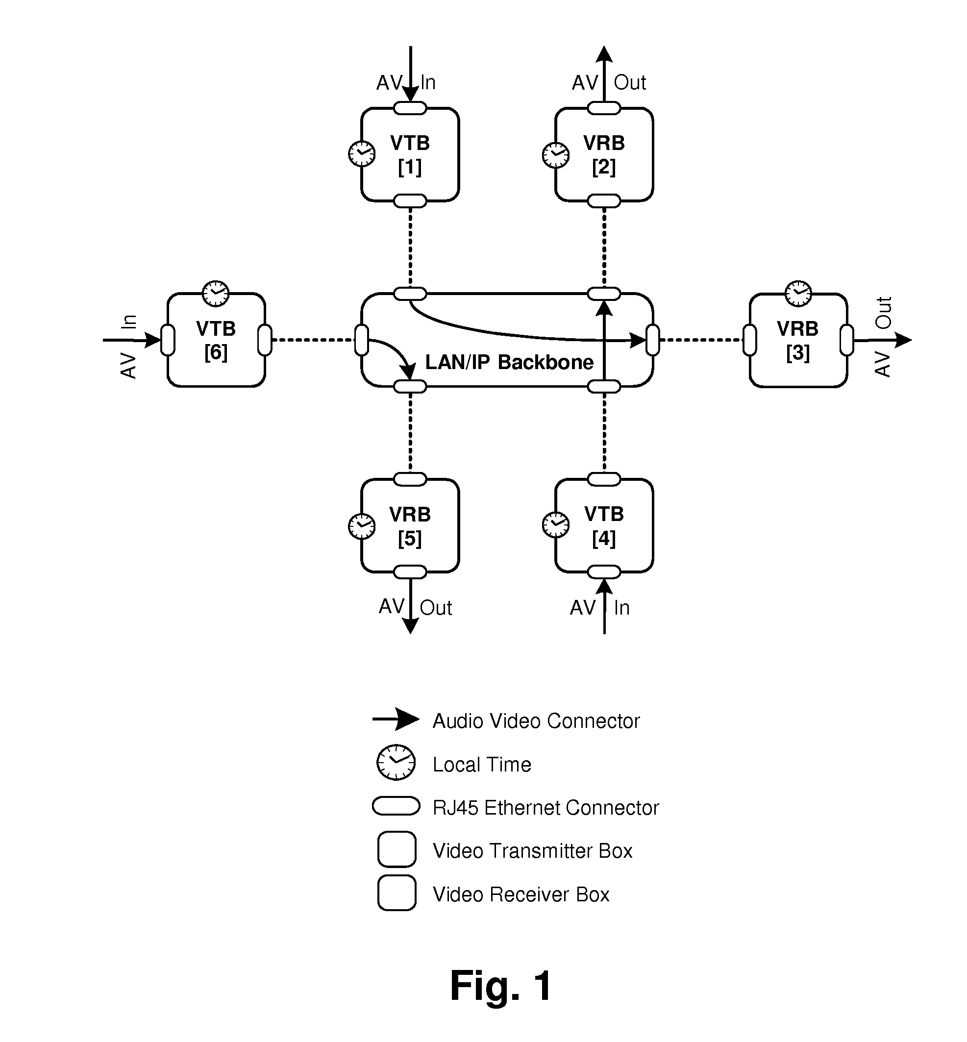
[0049]FIG. 2 a single pair of a VTB and a VRB;

[0050]FIG. 3 a “broadcasting” arrangement with a single VTB and two VRBs

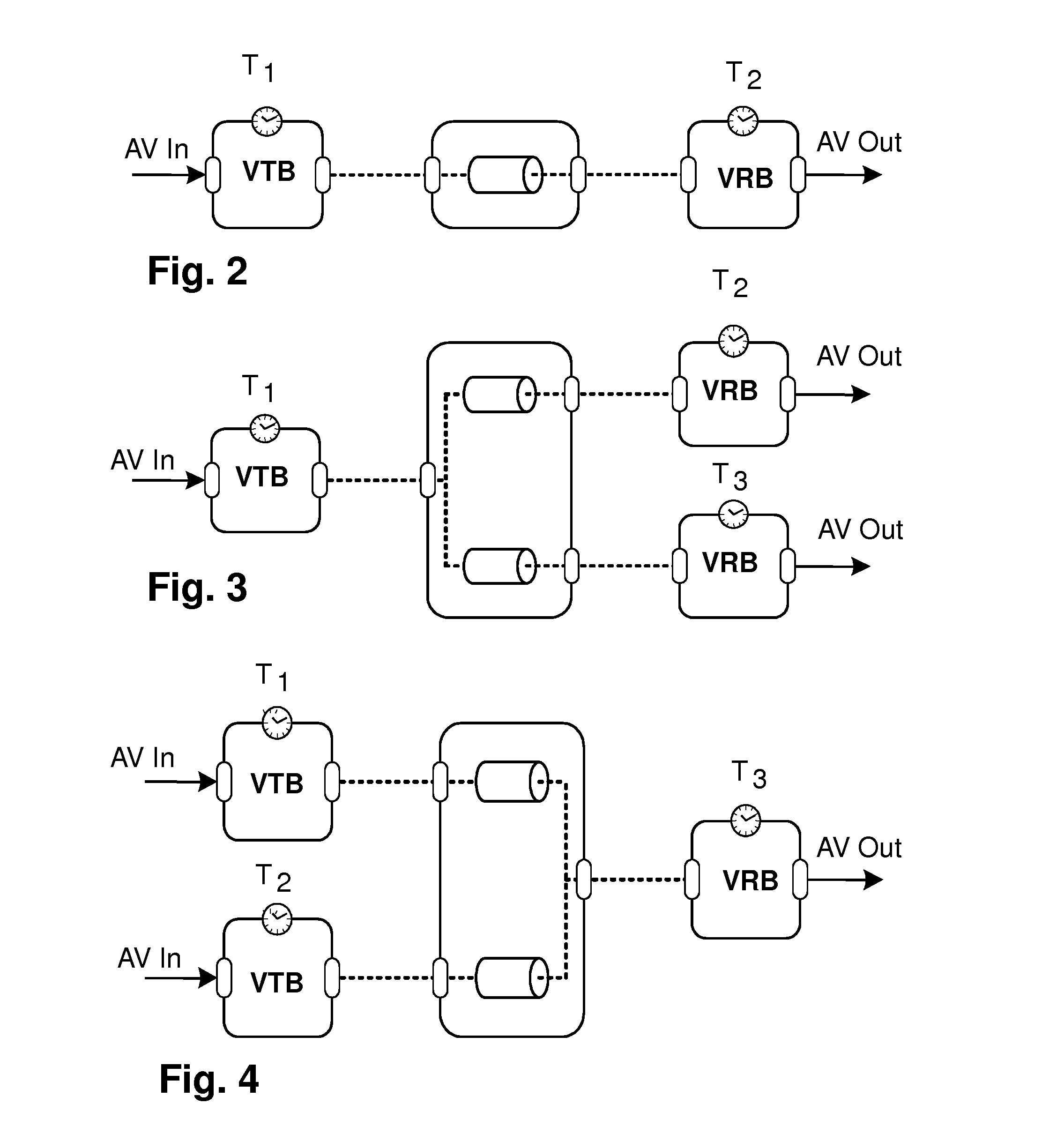
[0051]FIG. 4 an “inverse broadcasting” layout with two VTBs and one VRB;

[0052]FIG. 5 a pair of a typical VTB and a typical VRB showing their respective modular structure;

[0053]FIG. 6 the timing system on a baseboard, as used for a VRB;

[0054]FIG. 7 details of a video timing generator on a baseboard;

[0055]FIG. 8 details of an audio rate matching circuit on a baseboard;

[0056]FIG. 9 details of an audio timing generator on a baseboard;

[0057]FIG. 10 a block diagram of a typical implemented baseboard with its physical components;

[0058]FIG. 11 a baseboard configured as VTB; and

[0059]FIG. 12 a baseboard configured as VRB.

[0060]The system described in the ...


PUM


Abstract

The system transmits High Definition (HD) video/audio data, e.g. a JPEG2000-compressed video stream multi-channel audio stream, over a packet switching network, e.g. an Ethernet or IP network. Both the transmitter unit VTB and the receiver unit VRB feature a modular structure consisting of a base module or baseboard common to both units and one or more exchangeable adapter cards attached to or inserted into the baseboards to perform selected functions. The basebord is unitary, i.e. identical for both the VTB and the VRB; its components are activated depending upon the baseboard being in a VTB or a VRB. Each card is unique and earmarked and serves a specific purpose, e.g. for video coding and decoding, SMPTE processing, clocking/re-clocking, audio embedding/extraction. Upon inserting a card into a baseboard, the earmark is identified and the baseboard configured as transmitter or receiver baseboard. Functions in the baseboard can be implemented in Field Programmable Gate Arrays (FPGAs) and the network management, configuration, and/or control of the transmitting and/or receiving processes be performed by a softcore processors. This inventive combination of modular hardware/software results in a cost-effective, reliable, and fast system for transmitting large data volumes over packet switching networks.

Description

CROSS-REFERENCE TO RELATED APPLICATION [0001]This application claims priority under 35 U.S.C. §119 to U.S. Provisional Application No. 61 / 264,508, filed Nov. 25, 2009, the entire disclosure of which is incorporated herein by reference.TECHNICAL FIELD OF THE INVENTION [0002]The present invention concerns an improved system and method for the transmission of at least High Definition (HD) video / audio data, e.g. a JPEG2000-compressed video stream plus a compressed or uncompressed multi-channel audio stream, over a packet switching network, e.g. an Ethernet or IP network. Both the transmitter and the receiver feature a modular structure with at least one module common to both, preferably a base module or baseboard. Coding, and / or other processing at the transmitter is performed by exchangeable adapter modules, as is scaling, decoding, and / or similar processing at the receiver. These adapter modules are attached to the baseboard which provides power and selected functions necessary for th...

Claims


Application Information

Patent Timeline
IPC IPC(8): H04L12/56
CPCH04N21/226H04N21/426H04N21/4305H04N21/4342H04N21/64322
Inventor GELKE, HANS-JOACHIMBANFI, ANGELOROHR, RUDOLF
Owner BAROX KOMMUNIKATION
Why Eureka
Try Eureka