Motor control apparatus having a function to calculate amount of cogging torque compensation

a technology of motor control apparatus and compensation amount, which is applied in the direction of program control, dynamo-electric converter control, instruments, etc., can solve the problems of inability to calculate the proper amount of cogging compensation, so as to reduce the fluctuation of the motor speed

Active Publication Date: 2011-06-23
FANUC LTD
View PDF3 Cites 14 Cited by
  • Summary
  • Abstract
  • Description
  • Claims
  • Application Information

AI Technical Summary

Benefits of technology

[0015]According to the motor control apparatus of the present invention, since the proper amount of cogging torque compensation is calculated even in cases where components due to other factors than the cogging torque or components due to the gravitational torque are superimposed on the torque command being output during constant slow-speed feed operation, there is offered the effect that fluctuations in motor speed are reduced.

Problems solved by technology

Since the torque command thus contains fluctuating components due to gravity, if frequency analysis is performed directly on the torque command, it is not possible to calculate the proper amount of cogging compensation.
In this way, there are cases where components due to other factors than cogging torque (for example, components due to gravitational torque, etc.) are superimposed on the torque command being output during constant slow-speed feed operation, and in such cases, there arises a problem that a proper amount of cogging compensation cannot be calculated if the frequency analysis is performed directly on the torque command.

Method used


Image

  • Motor control apparatus having a function to calculate amount of cogging torque compensation
  • Motor control apparatus having a function to calculate amount of cogging torque compensation
  • Motor control apparatus having a function to calculate amount of cogging torque compensation

Examples


Embodiment Construction

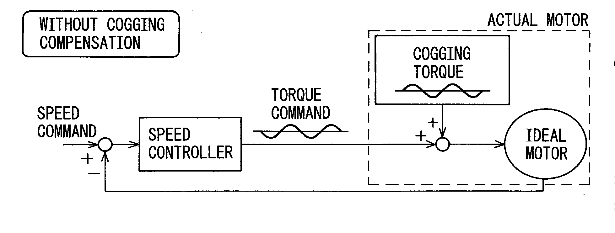
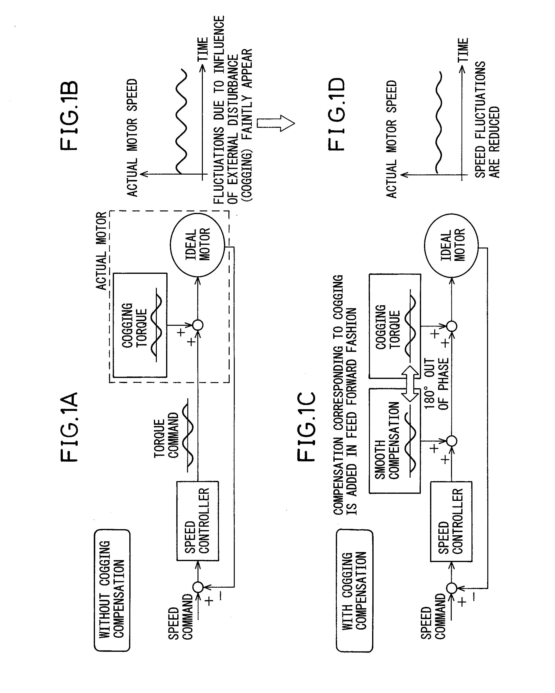
[0027]First, a description will be given of cogging compensation. FIGS. 1A, 1B, 1C, and 1D are diagrams explaining a method of cogging compensation. Since cogging torque can present an external disturbance in motor control, an actual motor operates by adding the cogging torque to the torque command given from a speed controller and by applying the result to an ideal motor, as illustrated in FIG. 1A. As a result, fluctuations due to the influence of the cogging torque as the external disturbance faintly appear in the actual motor speed, as illustrated in FIG. 1B. In the cogging compensation, the torque command is corrected by obtaining the amount of torque compensation in a 180° out of phase relationship with the cogging torque, as illustrated in FIG. 10. This cogging compensation serves to reduce fluctuations in the actual motor speed, as illustrated in FIG. 1D.

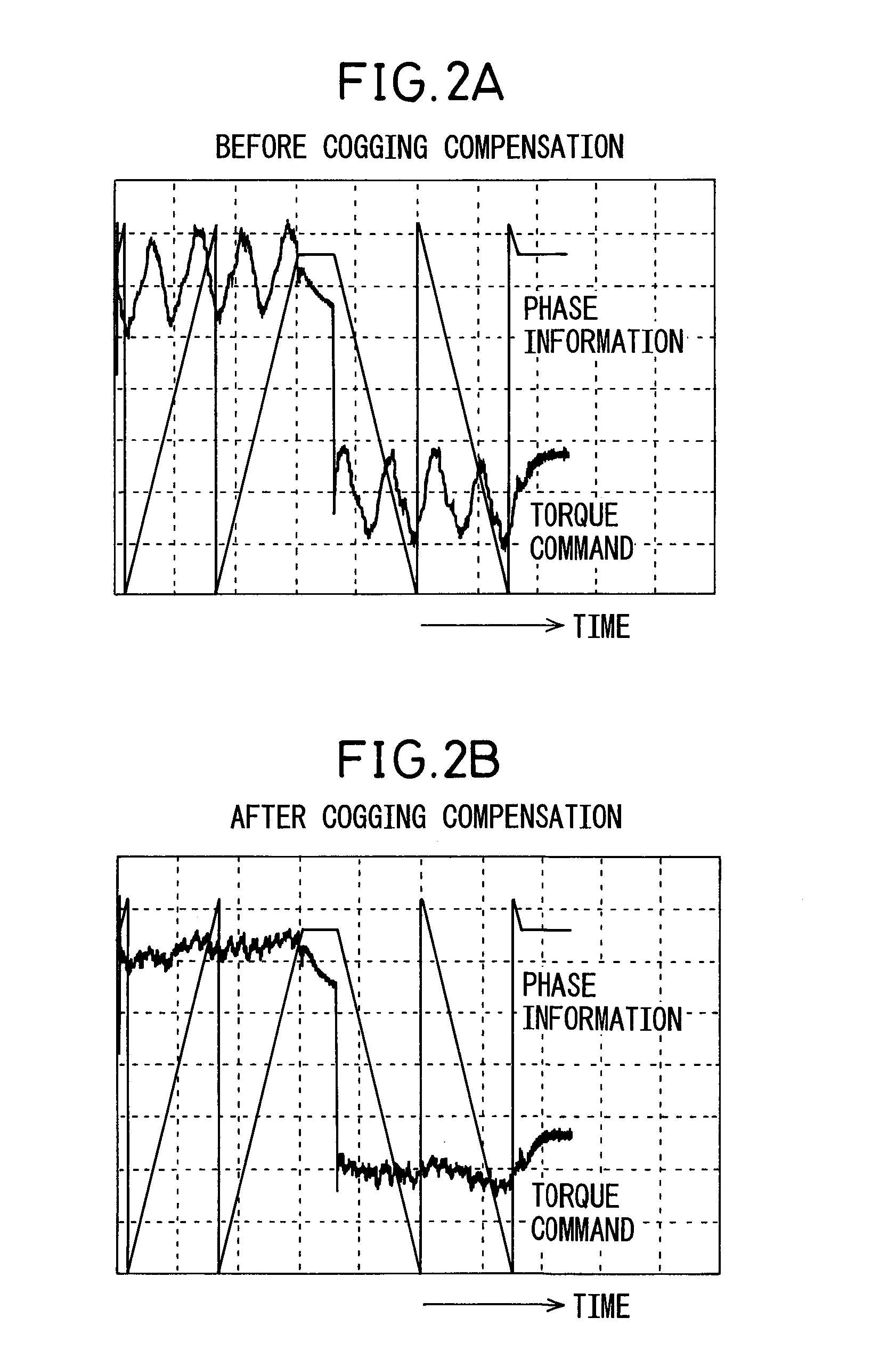
[0028]FIGS. 2A and 2B are diagrams showing torque command waveforms before and after the cogging compensation, respectively...


PUM


Abstract

A motor control apparatus that can calculate a proper amount of cogging torque compensation even in cases where components due to other factors than cogging torque (for example, components due to gravitational torque, etc.) are superimposed on a torque command being output during constant slow-speed feed operation. The motor control apparatus includes: a torque command monitoring unit which monitors a torque command when the motor is caused to operate at a constant speed; an approximation calculation unit which calculates a torque command approximation component by approximation from the torque command monitored over an interval equal to an integral multiple of the cogging torque period of the motor; a second torque command calculation unit which calculates a second torque command by subtracting the torque command approximation component from the torque command; a second torque command frequency analyzing unit which extracts frequency components, each at an integral multiple of the fundamental frequency of the cogging torque, by performing frequency analysis on the thus calculated second torque command; and a cogging compensation amount calculation unit which calculates the amount of cogging compensation from the amplitude and phase of the extracted frequency components.

Description

BACKGROUND OF THE INVENTION[0001]1. Field of the Invention[0002]The present invention relates to a motor control apparatus equipped with a function that corrects a torque command by calculating the amount of compensation for canceling out cogging torque which can cause an external disturbance in motor control (such a compensation will hereinafter be referred to as cogging torque compensation or cogging compensation).[0003]2. Description of the Related Art[0004]In recent years, the use of a direct-drive motor as a motor for driving the rotating axis of a machine tool has been increasing in order to meet the demand for higher speed and higher precision. Generally, in the case of an axis connected to a direct-drive motor, cogging compensation is applied in order to improve the smoothness of feed motion, since this type of motor produces a greater cogging torque than a conventional motor with a shaft. In the cogging compensation, the amount of compensation is calculated by performing fr...

Claims


Application Information

Patent Timeline
Patent Type & Authority Applications(United States)
IPC IPC(8): B23Q5/04H02P29/00
CPCH02P23/14G05B2219/41138H02P6/10G05B19/404
Inventor IWASHITA, YASUSUKEOKITA, TADASHITEZUKA, JUNICHISUGIYAMA, KAZUYUKI
Owner FANUC LTD
Why Eureka
Try Eureka