Insulated Foot Pad for a Tripod

Active Publication Date: 2011-06-23
MARQUARDT SHERMAN +1
View PDF47 Cites 8 Cited by
  • Summary
  • Abstract
  • Description
  • Claims
  • Application Information

AI Technical Summary

Benefits of technology

[0007]The subject invention involves an insulated foot pad for a tripod foot or instrument foot. Each pad has two rigid plates which sandwich a piece of insulating foam. The plates provide the pad surface area and are constructed for minimal heat conductivity. For exa

Problems solved by technology

This can be a difficult task since surveys are conducted in the field under temperature extremes.
Problems occur when these tripods are set on snow or ice.
Similar problems occur when a tripod is placed on asphalt on a warm day.
These various feet however do not prevent the tripod from shifting as the feet melt through the surface on which they are placed.

Method used


Image

  • Insulated Foot Pad for a Tripod
  • Insulated Foot Pad for a Tripod
  • Insulated Foot Pad for a Tripod

Examples


Embodiment Construction

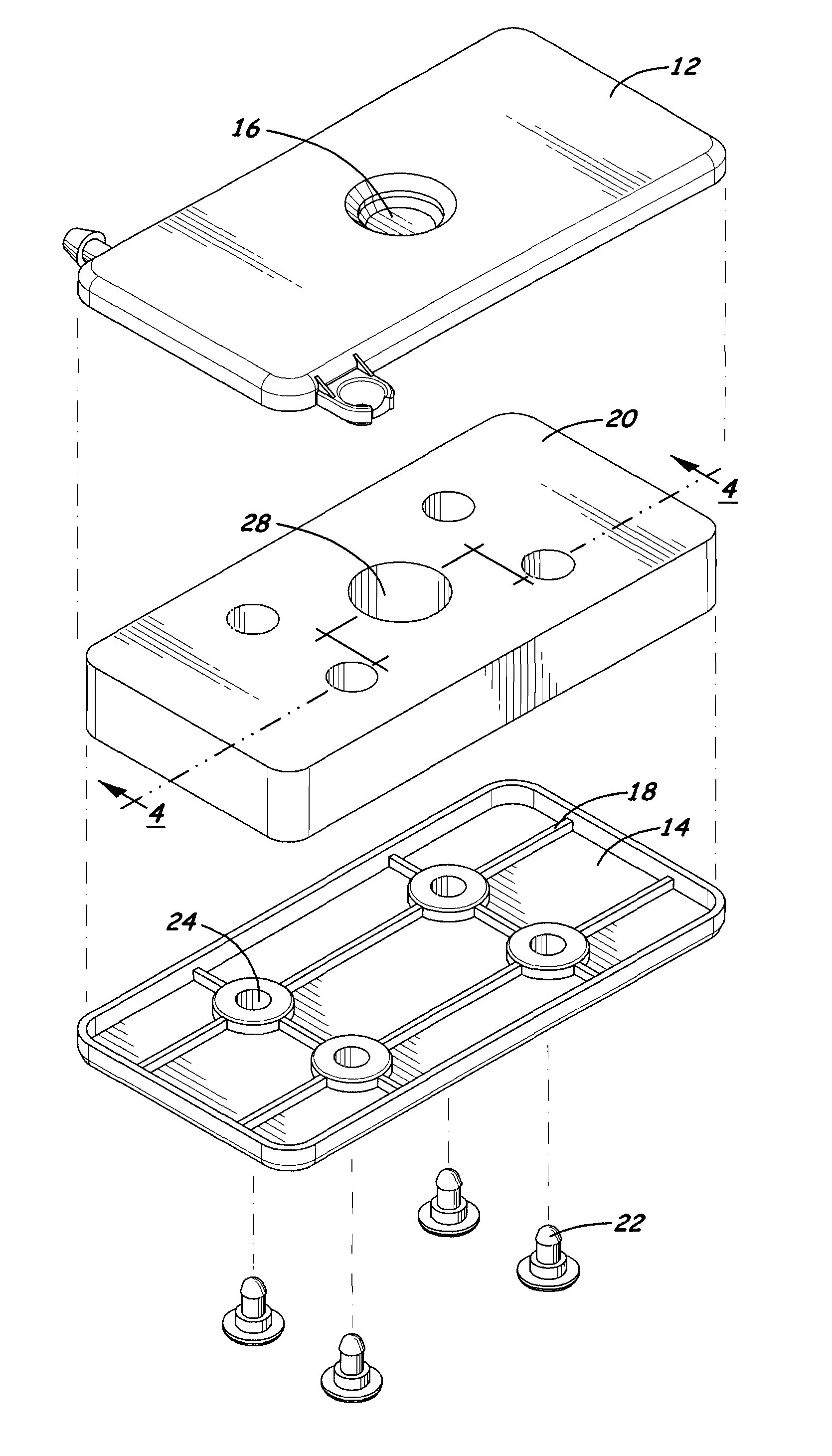
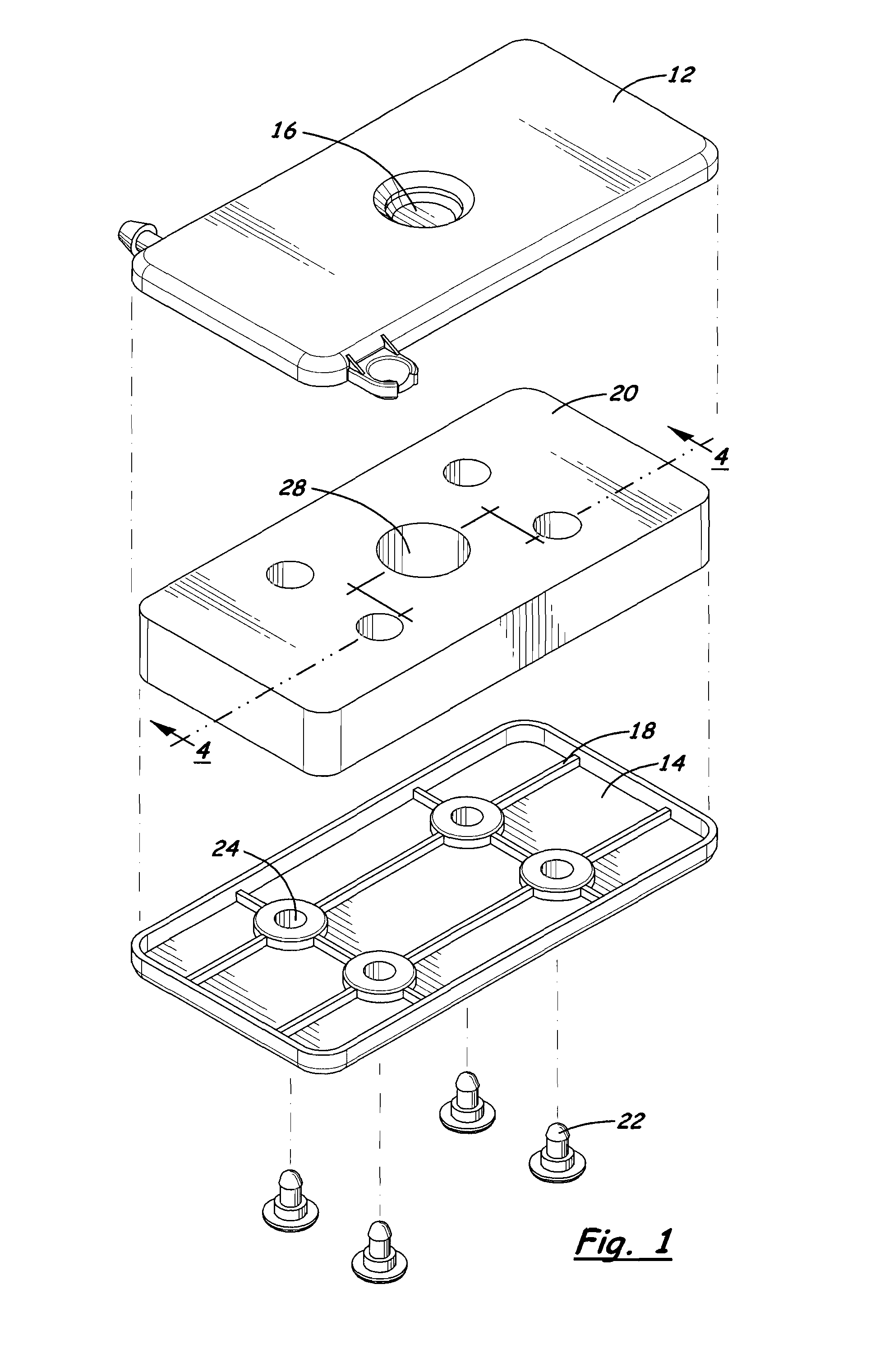
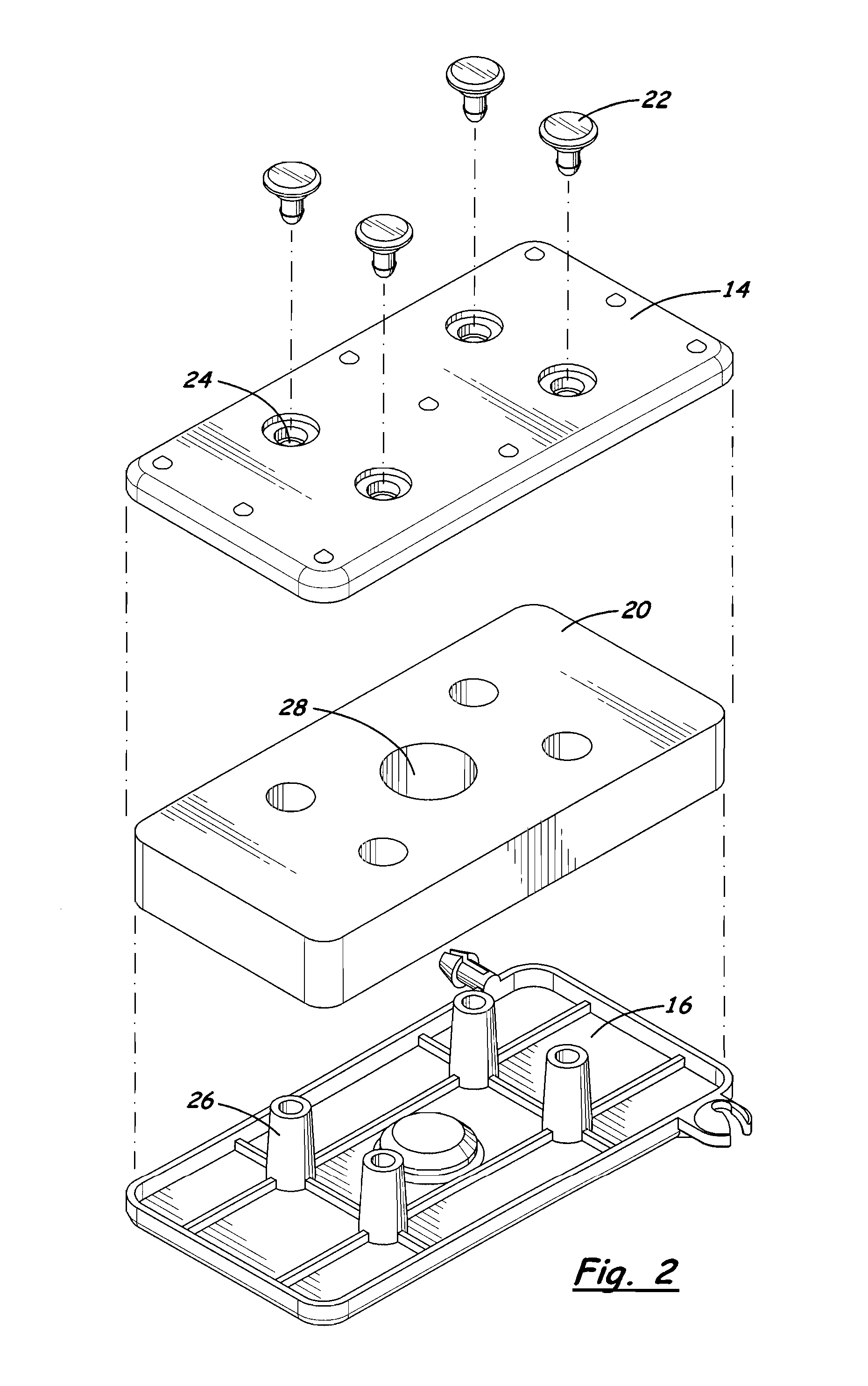
[0014]The invention involves an insulated foot pad for feet of an instrument. A block of insulating material is sandwiched between two plates that conduct heat poorly.

[0015]A preferred embodiment of the subject insulated foot pad 10 is shown in the appended figures. In an exemplified embodiment, the insulated foot pad is used to support a tripod foot on a surface. In the exemplified embodiment an insulating block of foam is sandwiched between two plastic plates. A top plate 12 contacts the foot of the tripod while a bottom plate 14 contacts the ground. The feet of a tripod for a field survey are most often spiked to anchor the tripod in soft ground. These often black spikes rapidly melt through ice and snow. The plates of the pad of the subject invention provide surface area for the tripod foot. The plates can be any shape or size. In the exemplified embodiment the plates are rectangular and are of sufficient size to offer surface area but are not too large to be cumbersome when car...


PUM


Abstract

An insulated foot pad for a tripod has an insulated block sandwiched between two plates. The plates are made of a material that is a poor conductor of heat. Tripod legs placed on the foot pads will not sink into the snow on sunny days nor into warm asphalt on hot days.

Description

CROSS-REFERENCE TO RELATED APPLICATIONS[0001]This application claims the benefits of U.S. Provisional Application No. 61 / 289,926, filed Dec. 23, 2009, the disclosure of which is hereby incorporated by reference in its entirety including all figures, tables and drawings.STATEMENT REGARDING FEDERALLY SPONSORED RESEARCH OR DEVELOPMENT[0002]Not applicableREFERENCE TO SEQUENCE LISTING, A TABLE, OR A COMPUTER PROGRAM LISTING COMPACT DISC APPENDIX[0003]Not applicableBACKGROUND OF THE INVENTION[0004]In the last several years land survey equipment has changed dramatically. Changes in technology have allowed this equipment to provide levels of accuracy never before achieved. Though survey equipment has changed, it is still mounted, as survey equipment has been for ages, on a tripod. It is still necessary that the tripod hold survey equipment steady and level to achieve accurate readings. This can be a difficult task since surveys are conducted in the field under temperature extremes. Most fie...

Claims


Application Information

Patent Timeline
IPC IPC(8): F16M13/00
CPCA47B91/06F16M11/36
Inventor MARQUARDT, SHERMANBYERS, GARY
Owner MARQUARDT SHERMAN
Why Eureka
Try Eureka