Structural element system and structural elements of such system for curtain facades, facade linings, sun rooms, soundproofing walls, fair buildings and the like

a structural element and structure technology, applied in the field of structural element systems and various structural elements of, can solve the problems of structural element systems not being comparable to systems, structural element systems being expensive, and sealing aging more quickly, so as to reduce manufacturing and assembly costs, and disrupt heat transport through sections

Inactive Publication Date: 2007-01-16
RIBIC WALTER
View PDF15 Cites 37 Cited by
  • Summary
  • Abstract
  • Description
  • Claims
  • Application Information

AI Technical Summary

Benefits of technology

[0025]According to the present invention, the heat transport via the sections is disrupted in that the framed flat elements, for example, windows, are not directly suspended from a post section but in that a seal of a hat-shaped cross-section and a holding section comprising one or several plastic stays with minimal heat conductivity is inserted between the post section and the flat elements. With such a so-called double-thermal separation it is prevented that the aluminum sections which engage the flat elements are in direct contact with a post section. Moreover, the post section is protected from direct contact with the ambient air.
[0026]It was found that the structural element system according to the invention can lower the manufacturing and assembly costs relative to known structural element systems by up to 70 percent. Even though the individual structural elements are partially more complex than the known structural elements, they can be produced, like most known structural elements, as extruded profiled sections so that their complex configuration is of no consequence. It is however important that the individual elements can be mounted particularly easily and quickly on site. The framed flat elements according to the invention are protected against damage during transport and can be mounted very quickly by simply suspending them.

Problems solved by technology

The frame sections which enclose, for example, two parallel windowpanes are difficult to manufacture which makes the structural element system expensive.
This structural element system requires that between two framed flat elements positioned adjacently or on top one another seals must be inserted which, however, as a result of thermal expansion in the case of frame sections generally made of aluminum are exposed to great loads.
They are constantly compressed and expanded which results in the seals aging more quickly so that at some point in time they will fall out.
However, they have the disadvantage in comparison to the above described systems that the flat elements must always be horizontally supported by the so-called latch and cannot be suspended in a floating arrangement.
Such structural element systems are therefore not comparable to the systems of the aforementioned kind.
In particular, mounting of the system of DE 195 26 671 A1 is very complex because the flat elements, i.e., in particular, two parallel windowpanes, are not pre-framed so that they cannot be simply suspended during assembly bust must be clamped on site.
A severe disadvantage, for aesthetic reasons, of such a post-and-latch construction is that first posts, which in the proper mounted state generally extend vertically, as well as second posts, which in the proper mounted state extends horizontally, are fully visible from the exterior of the facade while in the structural element system of the aforementioned kind the post elements are substantially fully covered by the framed flat elements and latches are entirety dispensed with; this has advantages in the so-called structural glazing (lining of the facade with glass) where the frame construction should be hardly visible in the finished facade.
This system has aesthetic as well as technical disadvantages.
In particular, there are unpleasant transitional at the interior between a post section and a section positioned between the framed flat elements and the post section.
Moreover, in this system the frame of the flat elements is problematic because generally the frame sections, which are extruded from aluminum, engage directly the flat elements so that, for example, aluminum and glass contact one another directly which can cause problems.
Moreover, in this structural element system extremely minimal manufacturing tolerances must be observed because otherwise particularly the horizontal abutting areas between two flat elements arranged on top one another will not be completely sealed so that moisture can penetrate.
Handling and mounting of such unframed windowpanes is a problem in particular when the flat elements must be quickly mounted outside.
There is a greater risk of injury for the personnel.
Moreover, the unframed flat elements can be easily damaged at their edge areas.
However, this system has a problem with regard to thermal insulation because the structural elements are made of aluminum sections which conduct heat comparatively well and because the framed flat elements are suspended directly from the post sections.
A further problem is the attachment of the post sections on a wall to be covered or on a different support, for example, a base member or a steal beam.
This increases the mounting expenditure on site significantly and makes assembly particularly at low ambient temperatures very difficult.
The known base members for mounting on the ground must be aligned very exactly relative to one another before attachment of the post sections; this requires very precise and thus time-consuming measuring.
A further problem of the known structural element systems is the framing of the flat elements by means of two-part profiled frames.
Also, the problem of the attachment of the post sections on the ground has not been solved in an visually satisfying way for every application situation.

Method used


Image

  • Structural element system and structural elements of such system for curtain facades, facade linings, sun rooms, soundproofing walls, fair buildings and the like
  • Structural element system and structural elements of such system for curtain facades, facade linings, sun rooms, soundproofing walls, fair buildings and the like
  • Structural element system and structural elements of such system for curtain facades, facade linings, sun rooms, soundproofing walls, fair buildings and the like

Examples


Embodiment Construction

[0049]In the following, several embodiments, which are only to be viewed as exemplary and not as limiting, of structural elements and of a structural element system according to the invention will be explained in connection with the drawings.

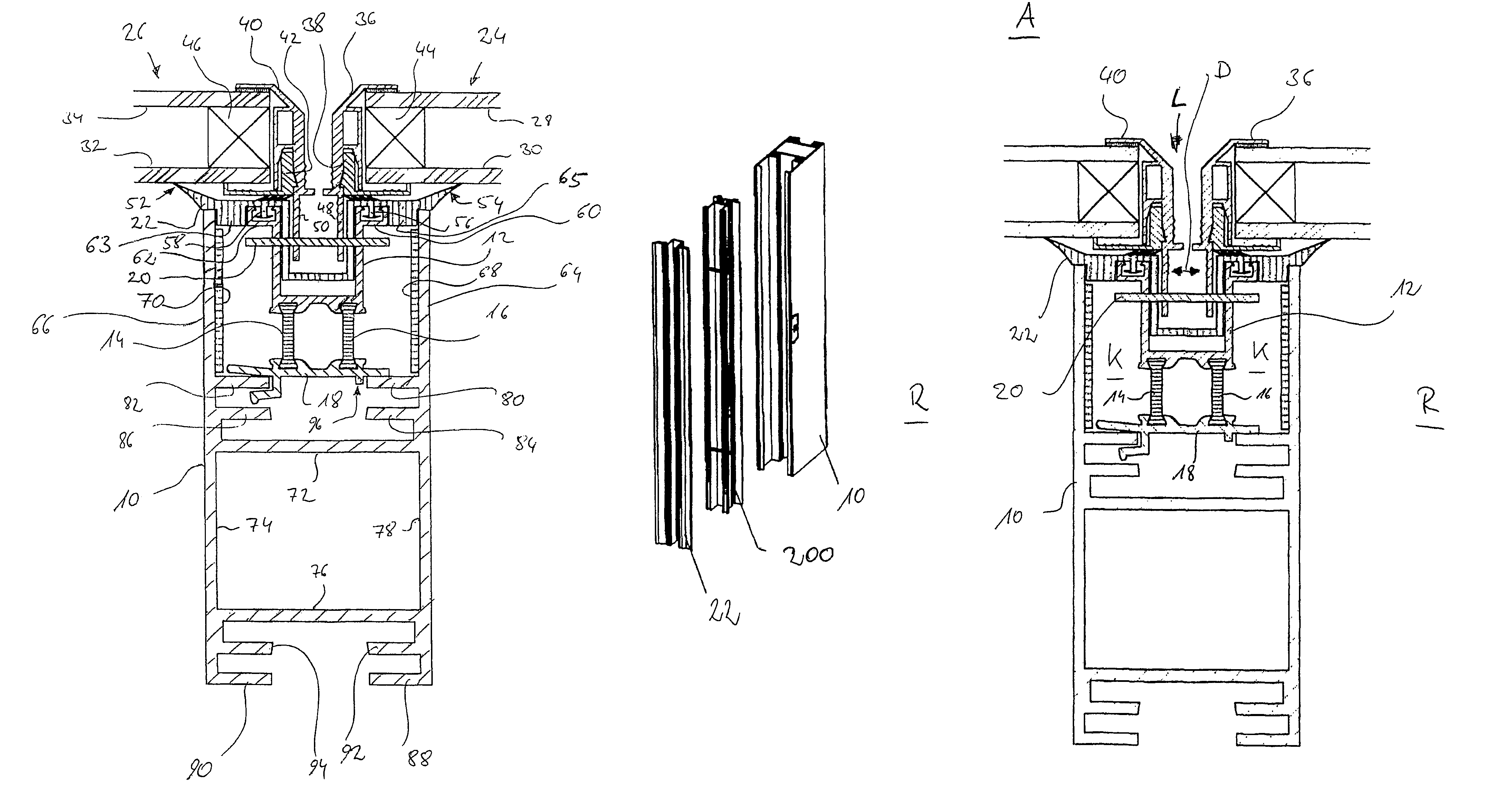
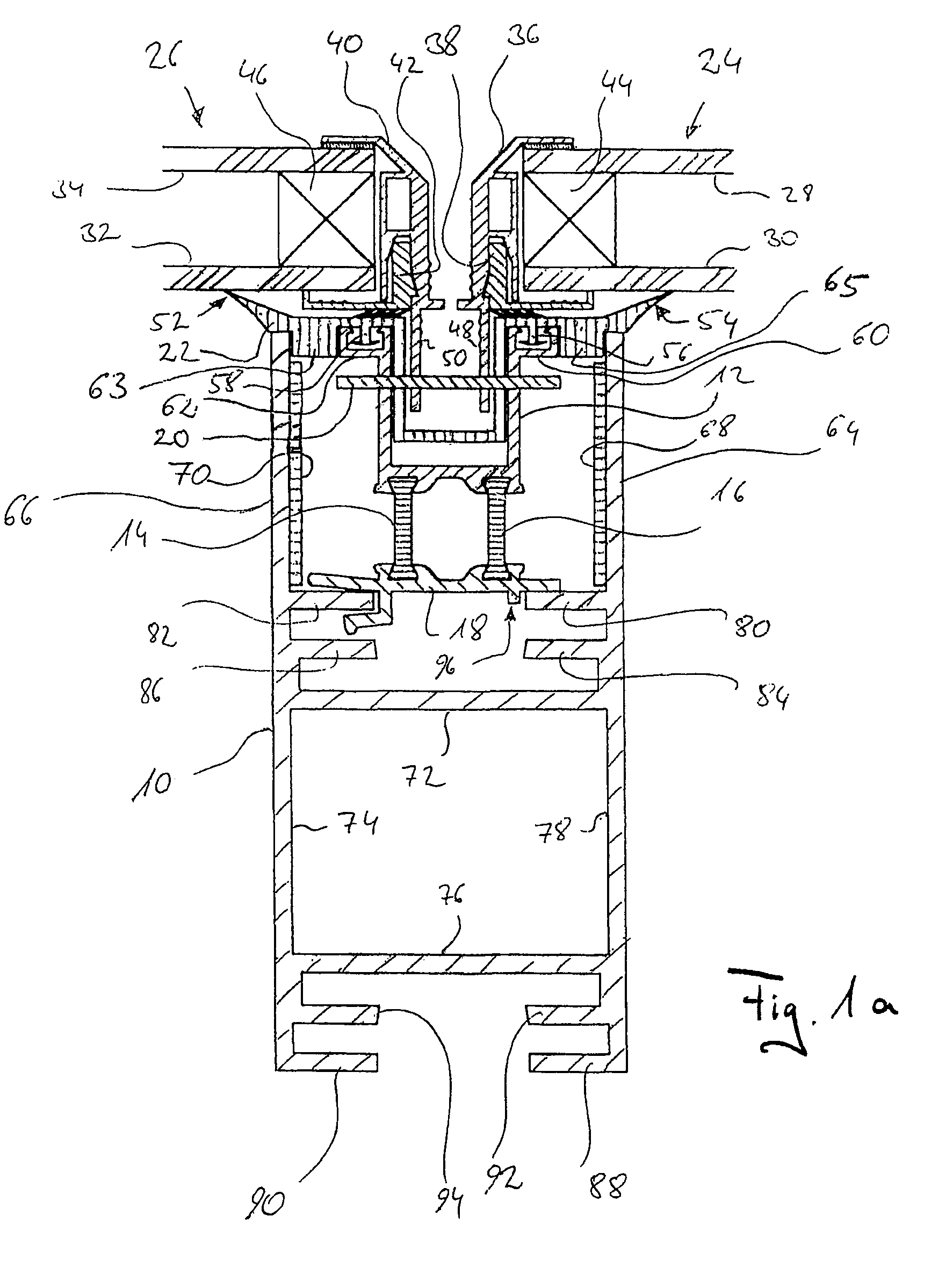
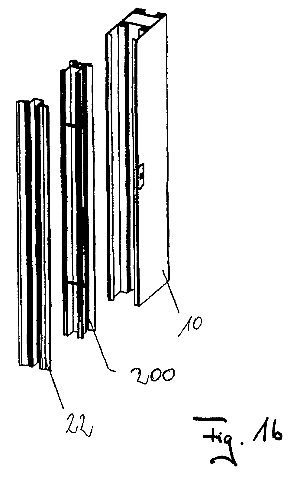
[0050]FIG. 1a shows a cross-section of different components of the system according to the invention in the mounted state: a post section 10; a holding section comprised essentially of a U-shaped receptacle 12, two connecting stays 14 and 16, and a fastening part 18, wherein this profile is illustrated in the detail in FIG. 11; a securing bolt 20 extending through the receptacle 12; a seal 22 inserted into the receptacle 12; and two flat elements identified at 24 and 26.

[0051]In the illustrated embodiment, the framed flat elements 24 and 26 are double-pane windows with two windowpanes 28 and 30; 32 and 34 which are framed by interlocking inner frame sections 38, 42 and outer frame sections 36, 40. Between the two windowpanes 28 and 30; 32 and 34...


PUM


Abstract

A structural element system for the construction industry has post sections, framed flat elements, holding sections, and seals, wherein, for thermal insulation of the post sections and the framed flat elements, the holding sections are attached on the post sections, wherein the framed flat elements are attached to the holding sections, and wherein the seals together with the post sections form chambers. In the mounted state of the structural element system, the holding sections are enclosed in the chambers. The post section is a box section having at least one rectangular box for securing the holding sections, respectively, wherein the rectangular box has on two parallel outer sides at least two holding lips for securing the holding sections or a connecting member. The system can be used to erect curtain facades, facade linings, transparent roofs, sunrooms, soundproofing walls, fair buildings, carports and the like.

Description

CROSS REFERENCE TO RELATED APPLICATIONS[0001]This application is a continuation application of international application PCT / DE02 / 00188 with an international filing date of Jan. 21, 2002, not published in English according to PCT Article 21(2), and now abandoned.BACKGROUND OF INVENTION[0002]The invention relates to a structural element system and various structural elements of such a structural element system for the construction industry applicable for constructing curtain facades, facade linings, transparent roofs, sunrooms, soundproofing walls, fair buildings, carports and the like. In particular, the invention relates to a post section, a holding section, a fastening element, a connecting member, a rigid connecting element, a jointed connecting element, a multi-pad base member, a profiled strip, a seal, a frame section, and a two-pad profiled frame for frame flat elements for curtain facades, facade linings, transparent roofs, sunrooms, soundproofing walls, fair buildings (exhib...

Claims


Application Information

Patent Timeline
Patent Type & Authority Patents(United States)
IPC IPC(8): E04H3/00E04B2/96E06B3/54
CPCE06B3/5427E04B2/96
Inventor RIBIC, WALTER
Owner RIBIC WALTER
Why Eureka
Try Eureka