Indicator for surgical stapler

Inactive Publication Date: 2011-06-30
TYCO HEALTHCARE GRP LP
View PDF100 Cites 6 Cited by
  • Summary
  • Abstract
  • Description
  • Claims
  • Application Information

AI Technical Summary

Problems solved by technology

Advancement of the thrust bar may cause rotation of the indicator member.

Method used


Image

  • Indicator for surgical stapler
  • Indicator for surgical stapler
  • Indicator for surgical stapler

Examples


Embodiment Construction

[0030]Embodiments of the presently disclosed surgical stapler will now be described in detail with reference to the drawings, wherein like reference numerals designate corresponding elements in each of the several views. Throughout this description, the term “proximal” will refer to the portion of the instrument closer to the operator and the term “distal” will refer to the portion of the instrument further from the operator.

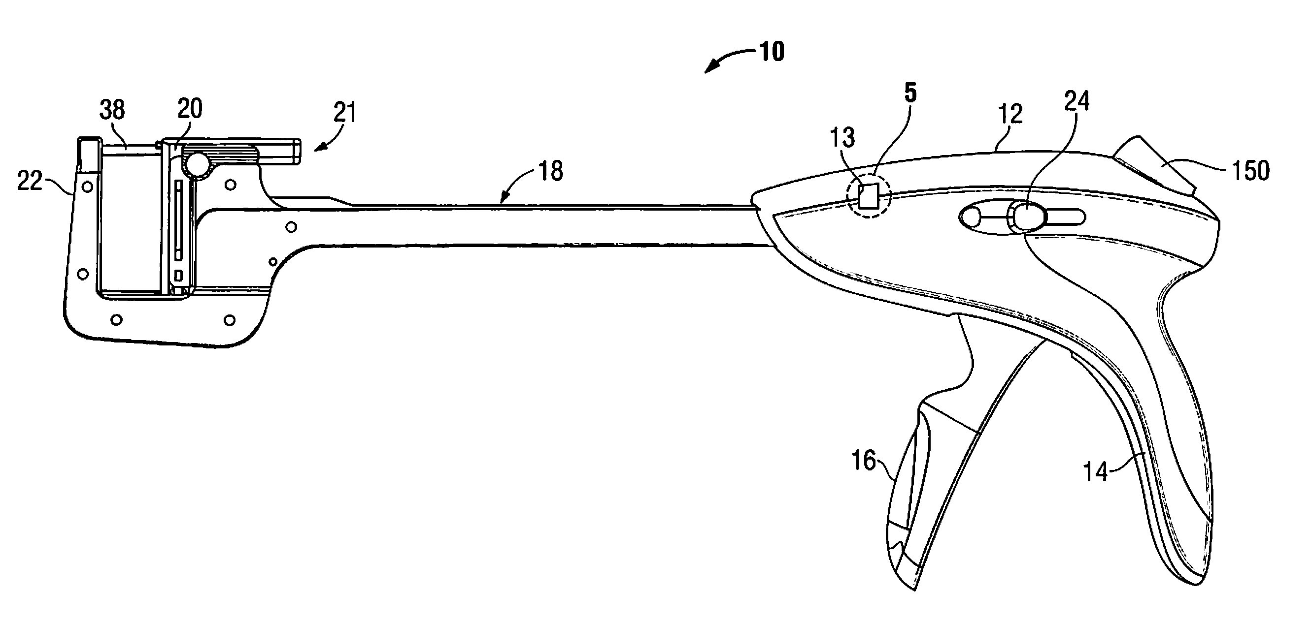
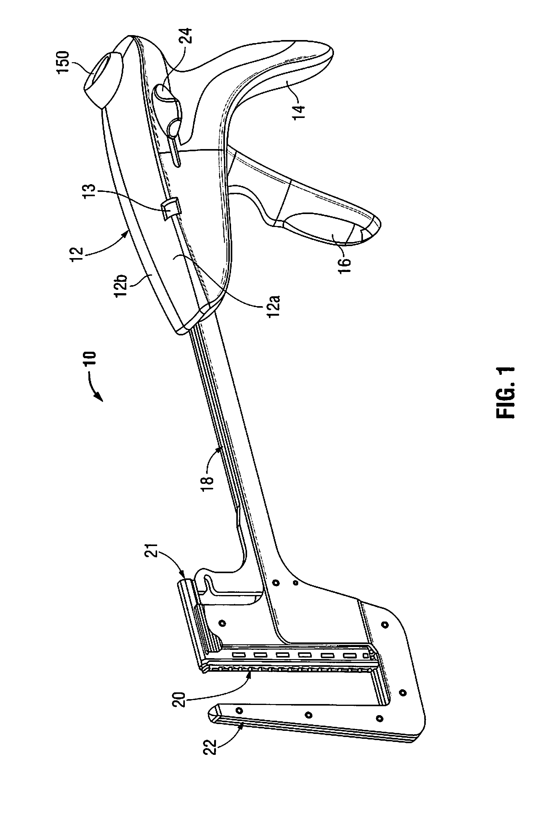
[0031]With reference to FIG. 1, a surgical stapling device according to an embodiment of the present disclosure is shown generally as surgical stapler 10. Surgical stapler 10 includes a body 12 defining a stationary handle 14, a pivotable trigger 16, an elongated central body portion 18, a cartridge assembly 20 and an anvil assembly 22. A thumb button 24 is slidably positioned on each side of body 12. Thumb buttons 24 are movable distally to manually advance an alignment pin 38 (FIG. 4) from alignment pin assembly 21 into engagement with anvil assembly 22 to cap...


PUM


Abstract

A surgical stapler for visually indicating to a user the stage of operation of the stapler. The surgical stapler includes a body, a stapling assembly positioned on a distal end of the body including a cartridge assembly and an anvil assembly, and a thrust bar slidably disposed within the body. The thrust bar is configured to advance distally from a retracted position to a first advanced position during approximation of the cartridge assembly towards the anvil assembly and advance further to a second advanced position to cause the release of staples from the cartridge assembly. An indicator member is connected to the thrust bar and configured to provide visual indication to a user upon complete approximation of the cartridge assembly and upon release of staples from the cartridge assembly.

Description

[0001]This application claims priority from provisional application Ser. No. 61 / 291,453, filed Dec. 31, 2009, the entire contents of which are incorporated herein by reference.BACKGROUND[0002]1. Technical Field[0003]The present disclosure relates generally to a surgical stapling apparatus and, more specifically, to a surgical stapling apparatus having a mechanism for indicating to a surgeon the condition of the stapler.[0004]2. Background of Related Art[0005]Surgical stapling instruments used for applying parallel rows of staples through compressed living tissue are well known in the art, and are commonly used, for example, for closure of tissue or organs prior to trans-section, prior to resection, or in anastomoses, and for occlusion of organs in thoracic and abdominal procedures.[0006]Typically, such surgical stapling instruments include an anvil assembly, a cartridge assembly for supporting an array of surgical staples, an approximation mechanism for approximating the anvil and c...

Claims


Application Information

Patent Timeline
IPC IPC(8): A61B17/068
CPCA61B17/072A61B17/068A61B2019/4857A61B2017/07214A61B2090/0811
Inventor NATARAJAN, ANANDRAMSELVARAJ, SRINIVASAN
Owner TYCO HEALTHCARE GRP LP
Why Eureka
Try Eureka