Tube fitting connection

a technology for fittings and pipes, applied in the direction of hose connections, joints with sealing surfaces, pipe joints, etc., can solve the problems of increasing the cost of initial assembly, time required, and increasing the cost of time, and achieve the effect of cost-effectiveness

Inactive Publication Date: 2011-07-14
GM GLOBAL TECH OPERATIONS LLC
View PDF17 Cites 10 Cited by
  • Summary
  • Abstract
  • Description
  • Claims
  • Application Information

AI Technical Summary

Benefits of technology

[0005]Compatible and attuned with the present invention, a cost effective tube fitting connection for interconnecting a source of fluid and an associated fluid receiving member to form a conduit for the transfer of the fluid therebetween, has been surprisingly discovered.

Problems solved by technology

The numerous parts and pre-assembly of such tubing and connector assemblies increase a cost thereof, as well as the time necessary to either attach or detach the tubing to the source and the associated fluid receiving member.
The increased time to attach the tubing and the connector assemblies increases a cost of initial assembly thereof and increases a cost associated with disassembly thereof when servicing any one of the tubing, the connectors, the source, and the associated fluid receiving member.

Method used


Image

  • Tube fitting connection
  • Tube fitting connection
  • Tube fitting connection

Examples


Embodiment Construction

[0014]The following description is merely exemplary in nature and is not intended to limit the present disclosure, application, or uses. It should also be understood that throughout the drawings, corresponding reference numerals indicate like or corresponding parts and features.

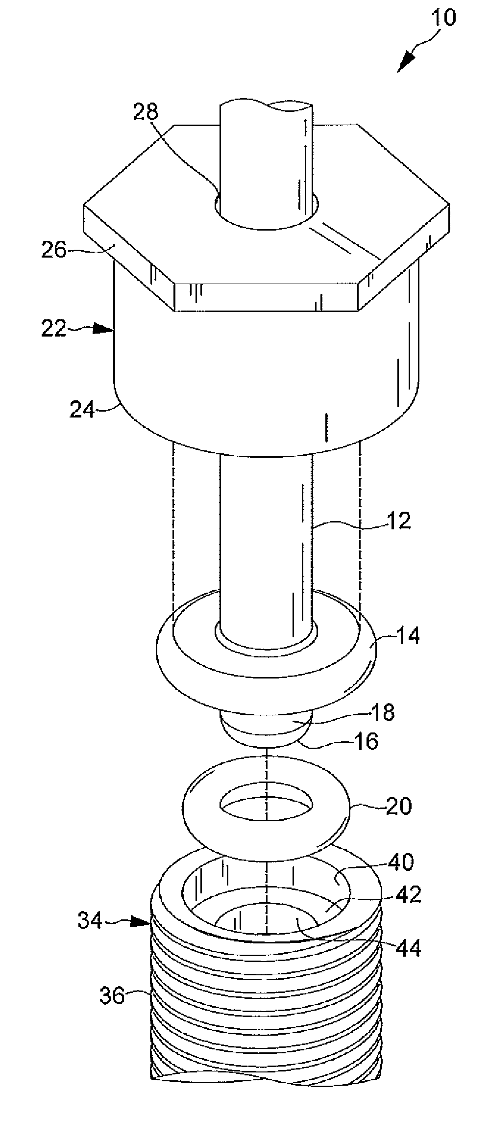
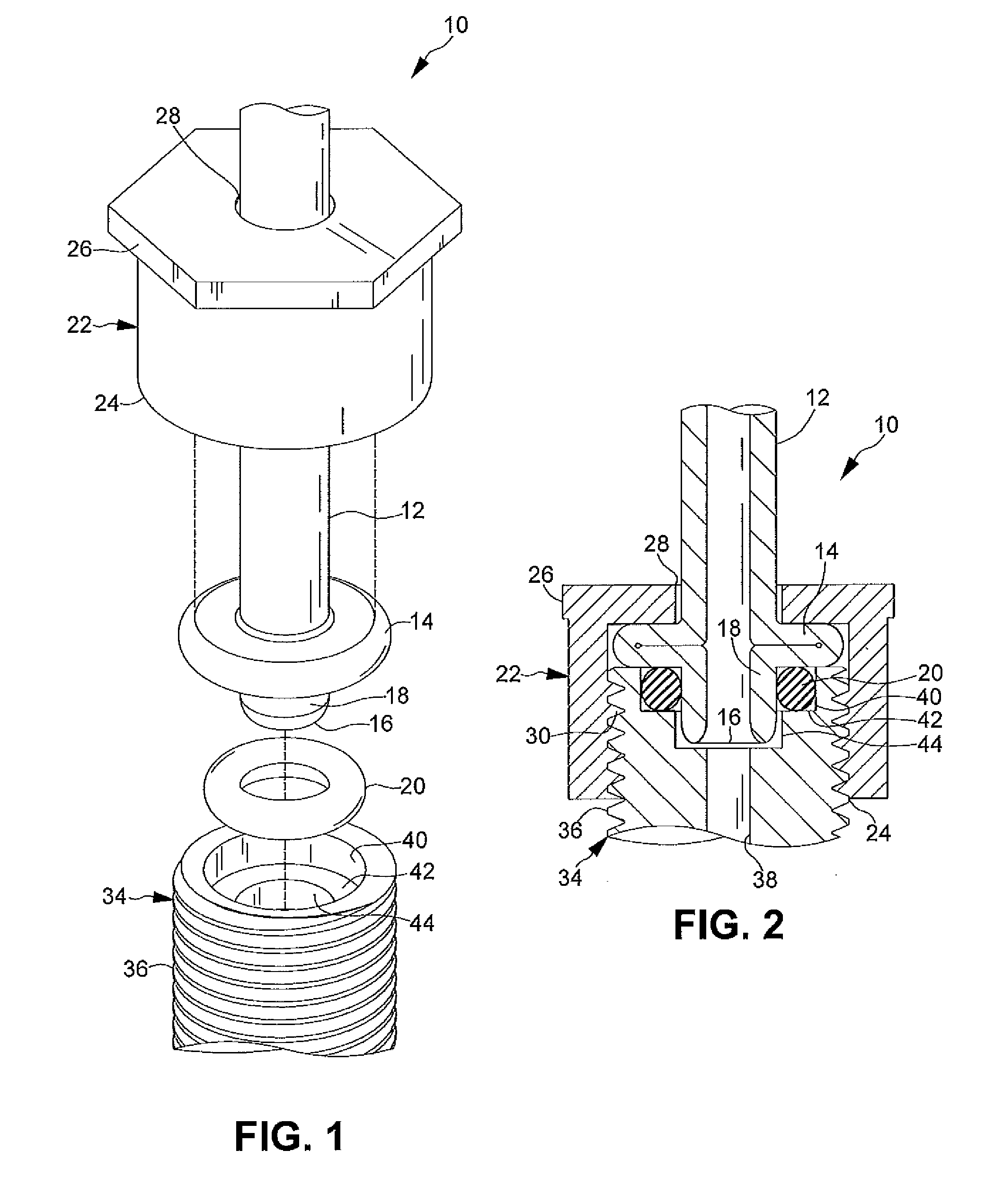
[0015]FIGS. 1-2 show a tube fitting connection 10 for a tube 12 according to an embodiment of the present disclosure. The tube fitting connection 10 includes a sealing member 20 and a gland nut 22 which cooperate with a male connector 34 to form a substantially fluid tight seal. The tube fitting connection 10 and the tube 12 form a conduit for the transfer of fluids between a source of a fluid (not shown) and an associated fluid receiving member (not shown) remotely located from the source.

[0016]The tube 12 includes a laterally outwardly extending flange 14 formed adjacent an end 16 of the tube 12. In the illustrated embodiment, the tube 12 is formed from a metallic material such as an aluminum, a copper, a b...


PUM

PropertyMeasurementUnit
pressuresaaaaaaaaaa
pressuresaaaaaaaaaa
metallicaaaaaaaaaa

Abstract

A tube fitting assembly is provided that includes a tube having a laterally outwardly extending flange formed adjacent an end thereof and a nipple portion between the flange and the end of the tube. A sealing member is disposed on and circumscribes the nipple portion of the tube. A gland nut is provided that includes an opening therethrough to receive the tube. The gland nut is adapted to be releasably coupled to a coupling member. The coupling member includes a counter bore formed therein to receive the sealing member and the nipple portion of the tube, wherein the gland nut abuts the flange of the tube to substantially secure the sealing member and the nipple portion within the counter bore to form a substantially fluid tight seal between the tube and the coupling member.

Description

FIELD OF THE INVENTION[0001]The present disclosure relates to a tube fitting connection and more particularly to a tube fitting connection for pressurized fluids.BACKGROUND OF THE INVENTION[0002]It is common practice to employ tubing between a source of a fluid and an associated fluid receiving member remotely located from the source, wherein the tubing forms a conduit for the transfer of fluids therebetween. The tubing typically includes connectors associated with ends of the tubing to facilitate an attachment of the ends of the tubing to the source and to the associated fluid receiving member.[0003]In certain applications, the fluid may be a high pressure fluid, wherein the tubing and the connectors are required to form and maintain a substantially fluid tight seal between the respective ends of the tubing and the source and the associated fluid receiving member. A number of tubing and connector assemblies have been employed to provide the substantially fluid tight connections. Va...

Claims


Application Information

Patent Timeline
Patent Type & Authority Applications(United States)
IPC IPC(8): F16L55/00
CPCF16L47/04F16L19/0286
Inventor SCHULZE, JORG
Owner GM GLOBAL TECH OPERATIONS LLC
Why Eureka
Try Eureka