
Sensor system

a technology of sensors and sensors, applied in the field of sensors, can solve the problem that the technology cannot adequately determine the amount of force (e.g., pressure) that is exerted on the touch screen by an operator without complicated mechanical systems

Active Publication Date: 2011-08-04
INTERLINK ELECTRONICS
View PDF5 Cites 58 Cited by
  • Summary
  • Abstract
  • Description
  • Claims
  • Application Information

AI Technical Summary

Benefits of technology

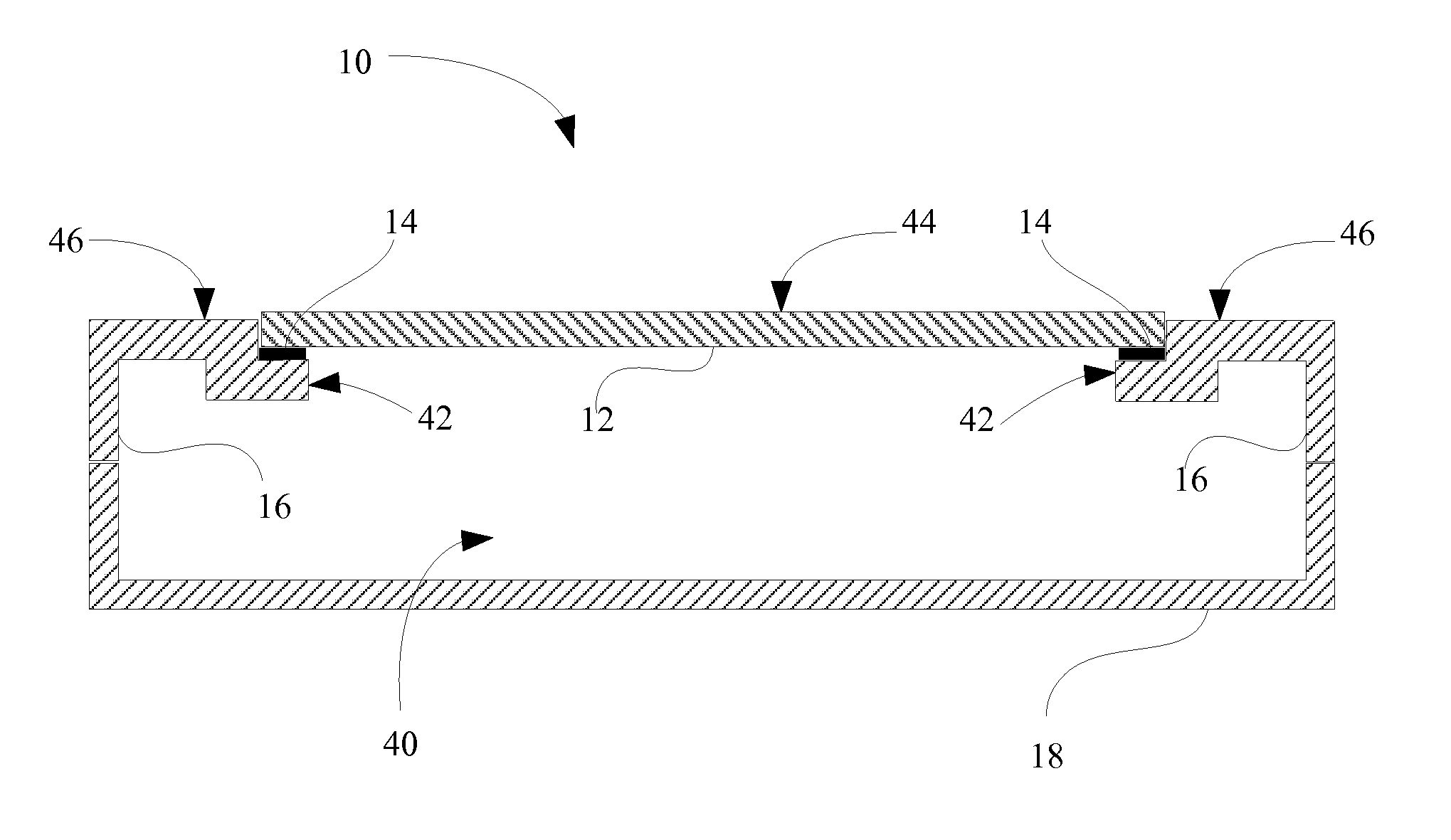
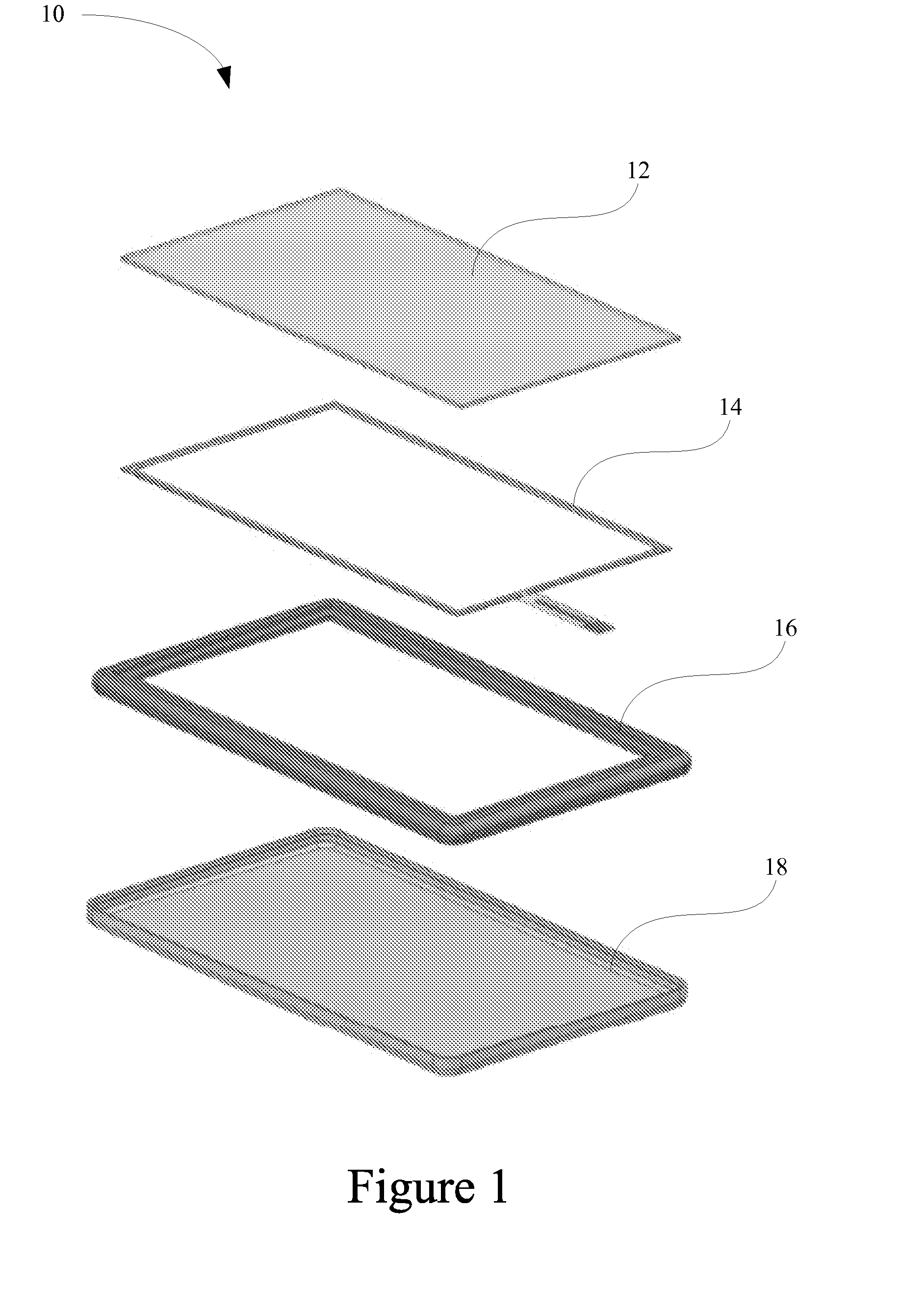
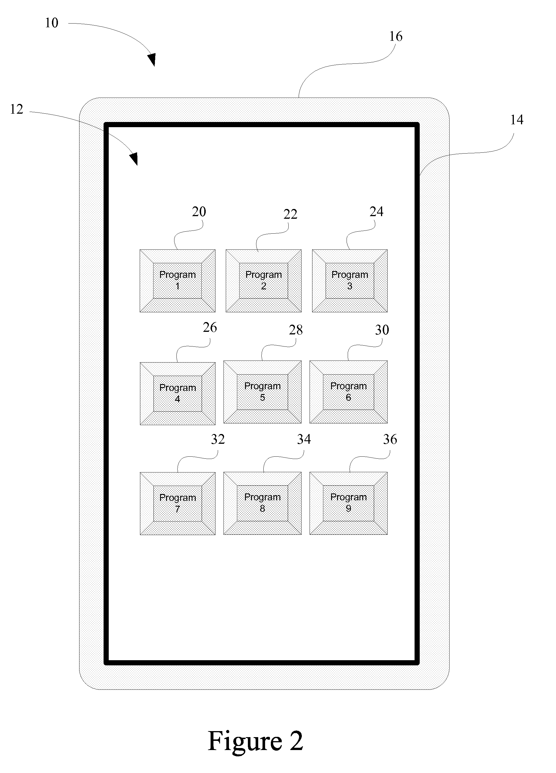
[0010]According to one embodiment, a sensor system including a touch screen and a force sensor is disclosed. The touch screen has a first and second surface and detects a first surface touch and converts it to data indicative of an X, Y coordinate position upon the touch screen first surface. The force sensor contacts the touch screen second surface and substantially extends around the perimeter of the touch screen second surface. The force sensor measures the force exerted by the first surface touch in the form of force data. The sensor system may further include a housing having a top surface, an opposing bottom surface and an inner cavity. The force sensor may contact the housing top surface and the touch screen second surface to form an inner cavity seal. The force sensor may be formed of a compressible elastomeric material. The sensor sys

Problems solved by technology

Although current touch screen technology provides X, Y coordinate location data, this technology is not able to adequately determine the amount of force (e.g., pressure) that is exerted on the touch screen by an operator without complicated mechanical systems.

Method used


Image

  • Sensor system
  • Sensor system
  • Sensor system

Examples


Embodiment Construction

[0016]As required, detailed embodiments of the present invention are disclosed herein; however, it is to be understood that the disclosed embodiments are merely exemplary of the invention that may be embodied in various and alternative forms. The figures are not necessarily to scale; some features may be exaggerated or minimized to show details of particular components. Therefore, specific structural and functional details disclosed herein are not to be interpreted as limiting, but merely as a representative basis for the claims and / or as a representative basis for teaching one skilled in the art to variously employ the present invention. With reference to the Figures, a more detailed description of one or more embodiments of the present application will now be provided.

[0017]Touch screens are designed to include many different types of sensor technologies. One type of touch screen currently used for portable devices includes a resistive or conductive material which relies on an ope...


PUM


Abstract

A sensor system includes a touch screen and a force sensor. The touch screen has a first and second surface and detects a first surface touch and converts it to data indicative of an X, Y coordinate position upon the touch screen first surface. The force sensor contacts the touch screen second surface and substantially extends around the perimeter of the touch screen second surface. The force sensor measures the force exerted by the first surface touch in the form of force data.

Description

CROSS-REFERENCE TO RELATED APPLICATIONS[0001]This application claims the benefit of U.S. provisional Application No. 61 / 300,988 filed Feb. 3, 2010. The disclosure of which is incorporated in its entirety by reference herein.BACKGROUND[0002]1. Technical Field[0003]One or more embodiments of the present application relate to a sensor system.[0004]2. Background Art[0005]Over the last several years manufactures of portable devices, such as tablet PCs, hand-held games, PDAs and cellular phones, have incorporated touch sensitive surfaces, or touchscreens, as the primary interface between the portable device and the user. The inclusion of touch screen devices continues to increase primarily as a result of the amount of software applications being developed and made available to purchasers of these portable devices.[0006]For example, Apple and Google have profited from increasing sales of their portable devices as a direct result of the increasing number of software applications available o...

Claims


Application Information

Patent Timeline
IPC IPC(8): G06F3/041G06F3/044G06F3/045G01L1/10
CPCG01L1/10G06F3/045G06F3/044G06F3/041G06F3/0446
Inventor BAKER, JEFFREY R.VLASKIN, VOLODYMYRSANCHEZ, CARLOS SOLISYAMAMOTO, MATTHEW FUMIOFLANNERY, DECLAN CHRISTOPHER
Owner INTERLINK ELECTRONICS
Learn More