Decompression switching valve

a switching valve and decompression technology, applied in the field of decompression switching valves, can solve the problems of large equipment size, high initial cost, complication, etc., and achieve the effects of simplifying and downsizing equipment, saving air consumption, and reducing equipment running cost and initial cos

Active Publication Date: 2011-08-11
SMC CORP
View PDF4 Cites 21 Cited by
  • Summary
  • Abstract
  • Description
  • Claims
  • Application Information

AI Technical Summary

Benefits of technology

[0014]For a decompression switching valve according to the present invention, a first spool and a second spool are slidably provided in one valve hole that penetrates through a main valve body, and a switching valve section having the first spool and a decompression valve section having the second spool are formed integrally with the main valve body. Thus, energy conservation by saving the air consumption, and simplifying and downsizing of equipment, can be simultaneously realized, which enables reduction in the running cost and the initial cost of equipment.

Problems solved by technology

However, it is necessary to provide the decompression valves 6, 125 in addition to switching valves for switching supply and exhaust air to / from the respective pressure acting chambers of the cylinder tube, causing problems of complication and a large size of equipment and a high initial cost.

Method used


Image

  • Decompression switching valve
  • Decompression switching valve
  • Decompression switching valve

Examples


Embodiment Construction

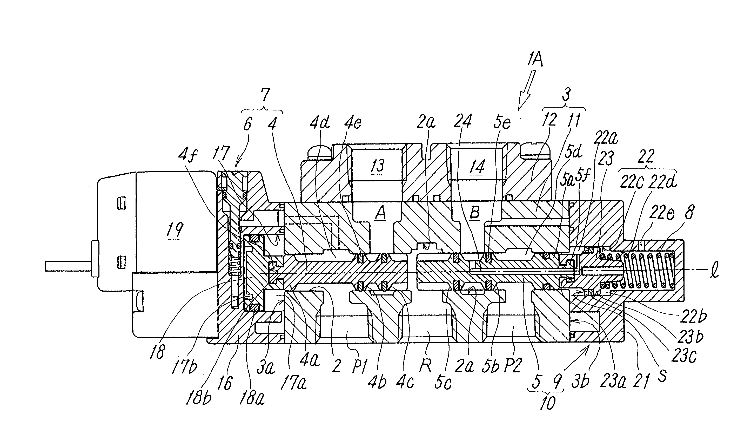
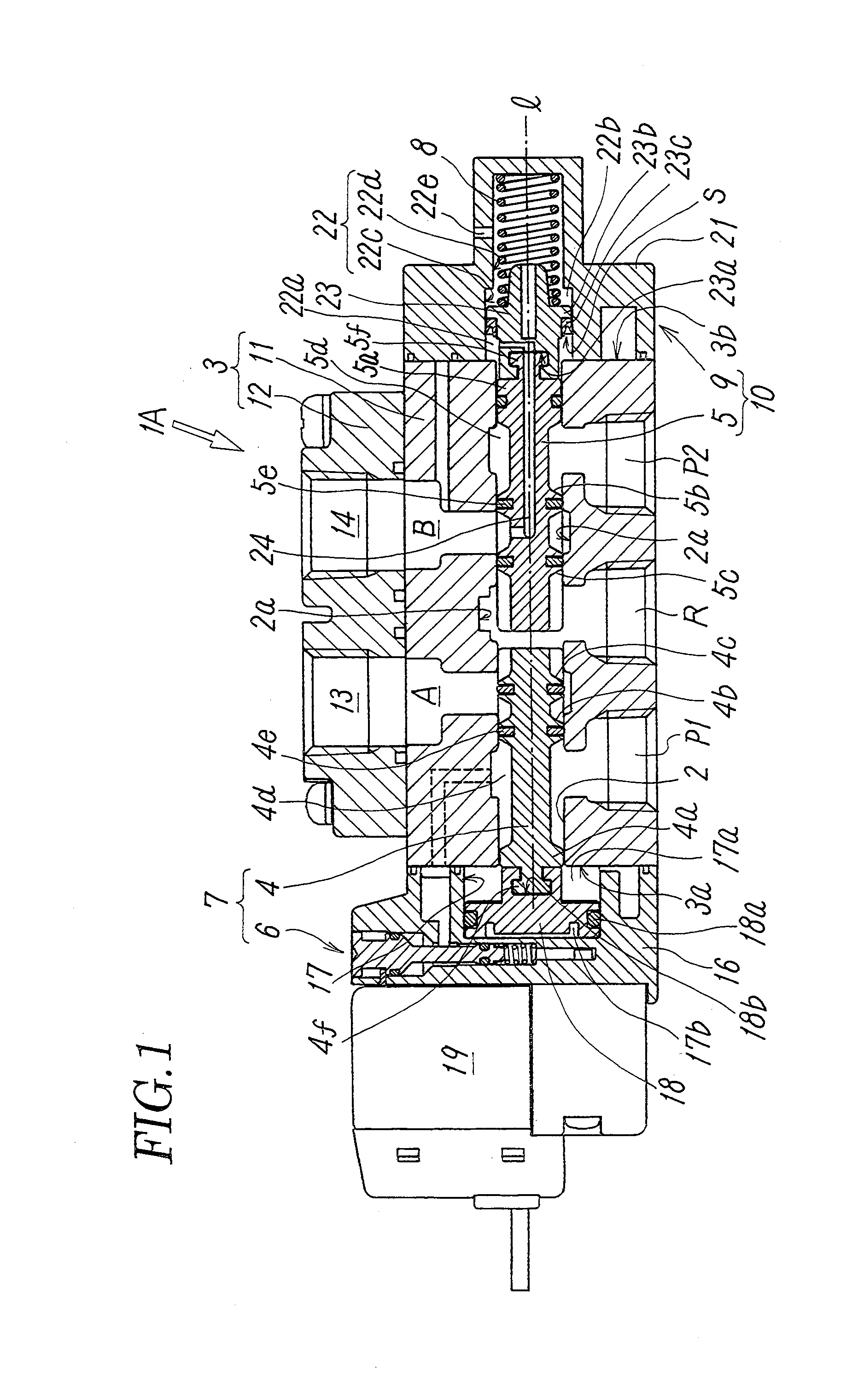
[0022]As shown in FIG. 1, a decompression switching valve 1A in a first embodiment according to the invention includes a main valve body 3 having one valve hole 2 that penetrates along the axis 1, a first air supply port P1, a second air supply port P2, a first output port A, a second output port B, and an air exhaust port R which are communicated with the valve hole 2, wherein the main valve body 3 has a first end 3a and a second end 3b which face opposite directions at the respective ends thereof with respect to the direction of the axis 1. In the valve hole 2, a first spool 4 is slidably provided on the first end 3a side in the valve hole 2, and a second spool 5 is provided slidably along the axis 1 on the second end 3b side with respect to the first spool 4, adjacent to the first spool 4, and attachably and detachably with / from the first spool 4.

[0023]Herein, the first output port A is arranged to connect with the first air supply port P1 or the air exhaust port R, depending on ...


PUM


Abstract

To provide a decompression switching valve that enables reduction in the running cost and initial cost, by saving of air consumption and simplifying and downsizing of equipment. A decompression switching valve includes one valve hole, a main valve body having air supply ports, a first output port, a second output port, and an air exhaust port which are communicated with the valve hole, and a first spool and a second spool which are slidably provided in the valve hole, adjacent to each other, wherein the first spool forms a switching valve section that selectively connects the first output port to an air supply port or the air exhaust port, and wherein the second spool forms a decompression valve section that reduces the pressure of compressed air having been input from the air supply port and outputs the pressure from the second output port.

Description

TECHNICAL FIELD[0001]The present invention relates to a switching valve having a decompression function, and, in particular, relates to a decompression switching valve integrally provided with a switching valve section and a decompression valve section that decompresses a supplied compressed air and outputs the decompressed air.BACKGROUND ART[0002]Hitherto, for example, air cylinders as an air pressure actuator have been widely used for a variety of automatic machines and have a structure where a piston with a fixed rod is reciprocally moved in a pressure chamber by supplying and exhausting compressed air. In general, compressed air is supplied and exhausted to / from such an air cylinder through a switching valve.[0003]In such an air cylinder, for a work stroke, a pressing stroke which is one of the two strokes of the piston moving reciprocally, a large driving force is necessary because an external load is applied to the rod. On the other hand, for a return stroke, by which the pist...

Claims


Application Information

Patent Timeline
Patent Type & Authority Applications(United States)
IPC IPC(8): F16K31/02
CPCF15B11/064F16K11/10F16K11/0716F16K11/07F15B13/043Y10T137/87225Y10T137/87193F15B11/06F16K31/36
Inventor MIYAZOE, SHINJISENBA, KATSUYUKI
Owner SMC CORP
Why Eureka
Try Eureka