Troffer-style light fixture with cross-lighting

a light fixture and cross-lighting technology, which is applied in fixed installation, lighting and heating apparatus, and support devices of lighting, etc., can solve the problems of compromising the efficiency of the fixture, the led device is not omni-directional, and the led-based troffer light fixture has some limitations, so as to soften the harsher light emitted, evenly distribute the light, and reduce the effect of lighting pollution

Active Publication Date: 2011-08-25
SIGNIFY HLDG BV
View PDF12 Cites 58 Cited by
  • Summary
  • Abstract
  • Description
  • Claims
  • Application Information

AI Technical Summary

Benefits of technology

[0005]This is directed to a LED-based troffer light fixture in which cross-lighting is used to soften the harsher light emitted by a LED package.
[0006]A troffer-style light fixture can be provided in which a light source is provided by a LED package or a LED module including several LED packages. To soften the light emitted by the fixture, at least some of the LEDs in the LED package can be directed at an angle out of the fixture, such that the light emitted by several LED packages can intersect and combine or mix outside of the fixture. In some embodiments, an interior surface of the troffer can be treated with one or more coatings so that some light emitted by the LED (e.g., light emitted towards the interior surface of the troffer) can reflect from the interior surface and be more evenly distributed from the fixture. For example, the interior surfaces of the troffer can be coated with two or more separate optical layers selected for special mixing of light to maximize performance and aesthetics. In some embodiments, the optical treatment can be selected based on color properties of the reflected and transmitted light of the troffer (e.g., to maximize color properties).
[0007]The LEDs can be distributed within the fixture using any suitable approach. In some embodiments, some LEDs can be positioned at opposite ends of the troffer, and oriented at an acute angle relative to a plane perpendicular to the troffer interior surface. The LEDs can then emit light across the troffer such that the emitted light can mix within and out of the fixture, and more evenly illuminate the environment of the fixture.
[0008]In some embodiments, the LED module used in a troffer can be removable. For example, the troffer can include a receptacle or receiving structure for receiving a LED module. The receptacle can have any suitable size, including for example one of several standard sizes. The particular size selected for a receptacle can be determined, for example, by the troffer size, or by the lighting requirements for the environment in which the fixture is installed. By allowing the LED module to be removable and replaced, the fixture can be easily serviced and used once an initial LED module reaches its useable lifetime.
[0009]The light emitted by a particular fixture can be adjusted using different approaches. In some embodiments, the size of a LED module placed in the fixture can be selected based on a desired light output. For example, a LED module can be selected based on the number of individual LED packages available in the module (e.g., using LED modules with different dimensions and a constant LED density, or LED modules with a variable LED density). In some embodiments, the fixture can include one or more features for limiting the light output by the LED module. For example, the receptacle can include one or more openings or slots through which light emitted by the LEDs can propagate. In some embodiments, the number of slots or openings can be adjusted based on the lighting requirements for the fixture environment. This approach can allow, for example, a same fixture to provide light at 30 lumens per watt or 80 lumens per watt.

Problems solved by technology

Contrary to a fluorescent light tube, however, a LED device is not omni-directional but instead may only emit light in no more than a 180 degree cone.
LED-based troffer light fixtures have some limitations, however.
To soften the harshness of LED light, diffusers with low transmission properties can be used, but such diffusers would compromise the efficiency of the fixture and eliminate the advantage of using LED-based troffer fixtures instead of fluorescent light tube-based troffer fixtures.

Method used


Image

  • Troffer-style light fixture with cross-lighting
  • Troffer-style light fixture with cross-lighting
  • Troffer-style light fixture with cross-lighting

Examples


Embodiment Construction

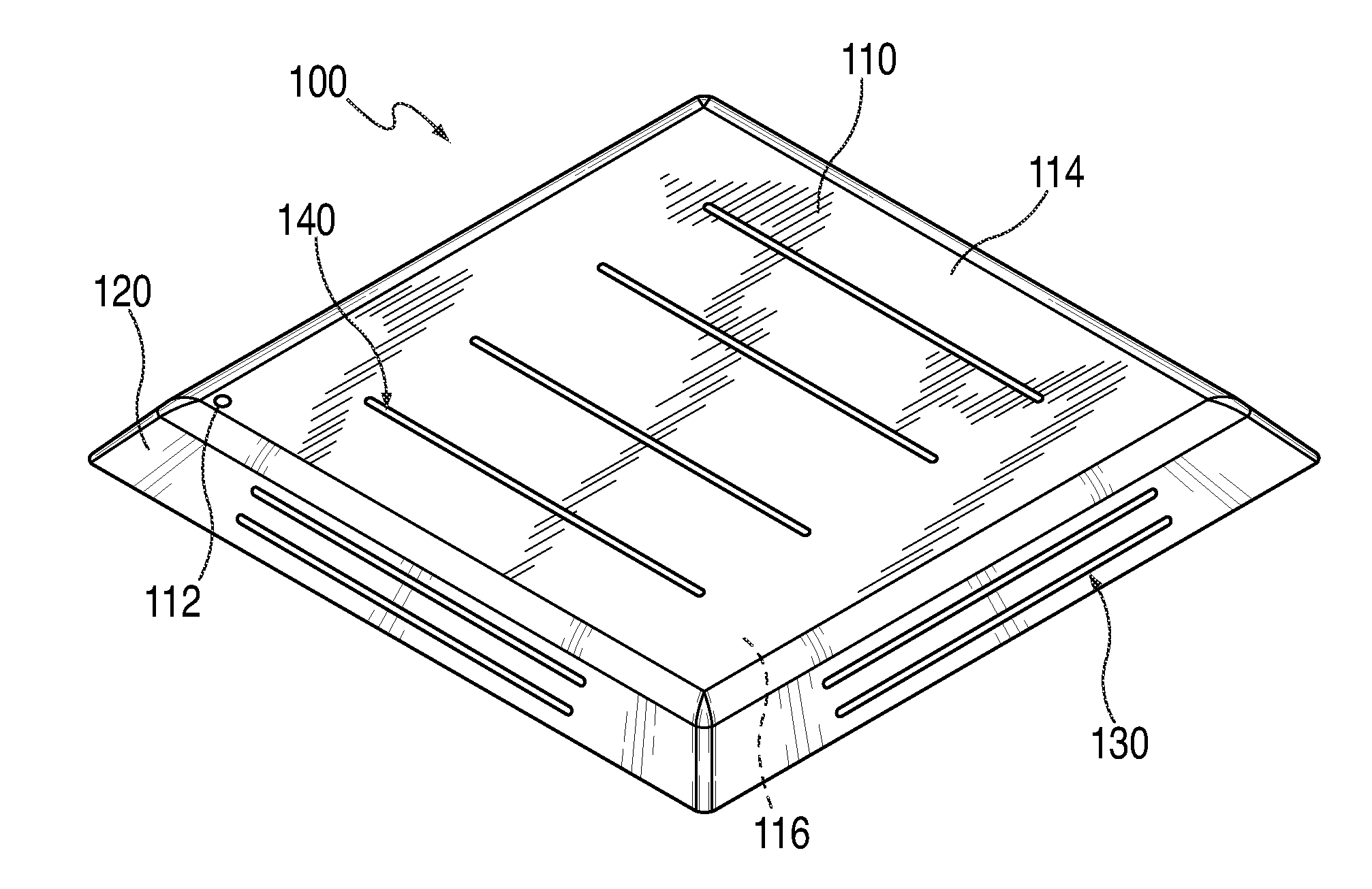
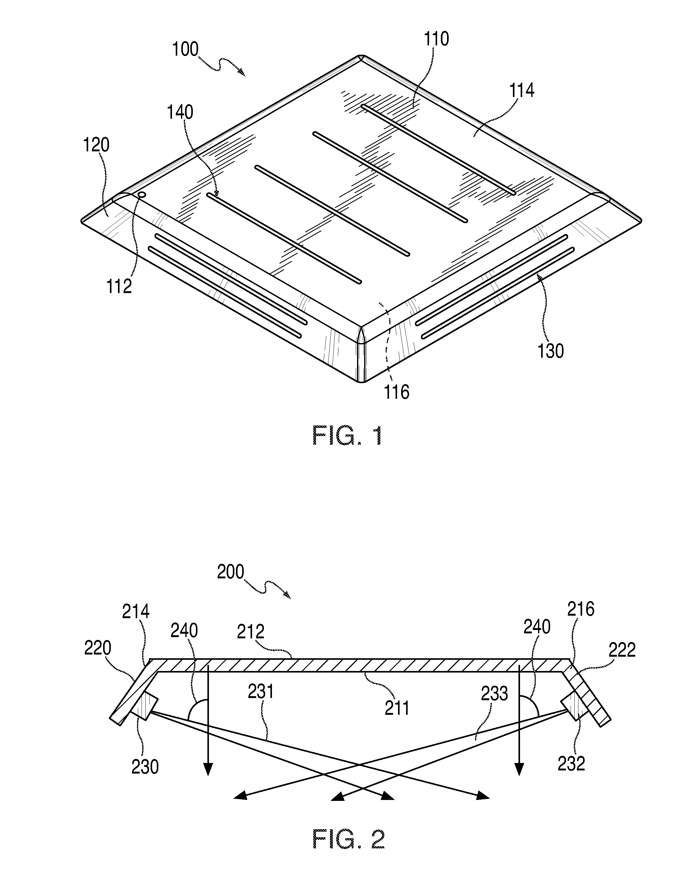
[0021]This is directed to a troffer-style fixture using a LED module to provide a light source. At least some of the LEDs in the module can direct light out of the troffer at an angle such that the light can combine and mix before reaching objects in the environment.

[0022]FIG. 1 is a schematic view of an illustrative troffer from for use in a LED-based fixture in accordance with one embodiment of the invention.

[0023]Fixture 100 can include frame 110 supporting a light source and directing the light out of the fixture. Frame 110 can be constructed from back plate 112 from which side walls 120 can extend. Back plate 112 can define a substantially planar surface serving as a base structure for the fixture. In some embodiments, back plate 112 can instead or in addition include a non-planar surface, such as a curved back surface. Back plate 112 can include internal surface 116 exposed to a LED light source, and external surface 114 exposed to the environment. In some embodiments, externa...


PUM


Abstract

This is directed to a troffer-style light fixture using a LED light to cross-light internal surfaces of the troffer. In particular, this is directed to a troffer-style fixture having several receptacles for receiving LED modules. The modules can be inserted in the fixture such that some light emitted by the LED modules is directed towards an opposite surface of the fixture, causing light from opposite LED modules to mix as light is emitted from the fixture (e.g., cross lighting the fixture environment. The resulting light transmitted and reflected by the troffer can have softer qualities than direct light emitted by a LED module, and enhance the aesthetic appeal of light provided by the fixture. In some embodiments, one or more optical treatments can be applied to internal surfaces of the fixture to enhance the light output by the fixture.

Description

BACKGROUND OF THE INVENTION[0001]This is directed to a troffer-style light fixture using cross-lighting. In particular, this is directed to using LED lights to cross-light the internal surface of a troffer and mix light.[0002]One of the most prolific commercial light fixtures is a fluorescent troffer fixture. This fixture includes a troffer forming a housing into which one or more fluorescent light tubes are inserted. The troffer includes a base surface from which side walls extend to form an open box. The fixture can include ballast (e.g., a power supply) for maintaining a desired orientation of the fixture when it is fixed to a surface (e.g., a ceiling). The fixture can include one or more acrylic lenses, diffusers or parabolic louvers for controlling the light emitted by the fluorescent tubes. Because fluorescent tubes emit omnidirectional light (e.g., in 360 degrees), the interior surface of the troffer fixture can include a reflector for redirecting up light (e.g., light emitte...

Claims


Application Information

Patent Timeline
Patent Type & Authority Applications(United States)
IPC IPC(8): F21S4/00H01J9/24
CPCF21K9/30F21S8/04F21Y2103/003F21Y2101/02F21V19/045F21K9/20F21Y2103/10F21Y2115/10F21V19/04
Inventor PEIFER, DONALD A.SANJURJO, MICHAEL A.
Owner SIGNIFY HLDG BV
Why Eureka
Try Eureka