Cold frame

a frame and cold technology, applied in the field of cold frames, can solve the problem of somewhat unsteady connection of the side walls of the container with the uprights

Active Publication Date: 2011-09-01
WUSTER HEINRICH
View PDF6 Cites 3 Cited by
  • Summary
  • Abstract
  • Description
  • Claims
  • Application Information

AI Technical Summary

Benefits of technology

[0007]According to the invention, in the case of a clamping device which connects two side wall elements to an upright, a clamping element may be provided which abuts against the inner sides of the hollow chamber panels on both side wall elements and is clamped betwee

Problems solved by technology

It is disadvantageous that, in addition to the large number of individual parts of the numerous pin-type connectors of the container that have carefully to be kept safe, the pin-type connectors that are put together are slightly movable within themselves because of the play tha

Method used


Image

  • Cold frame
  • Cold frame
  • Cold frame

Examples


Embodiment Construction

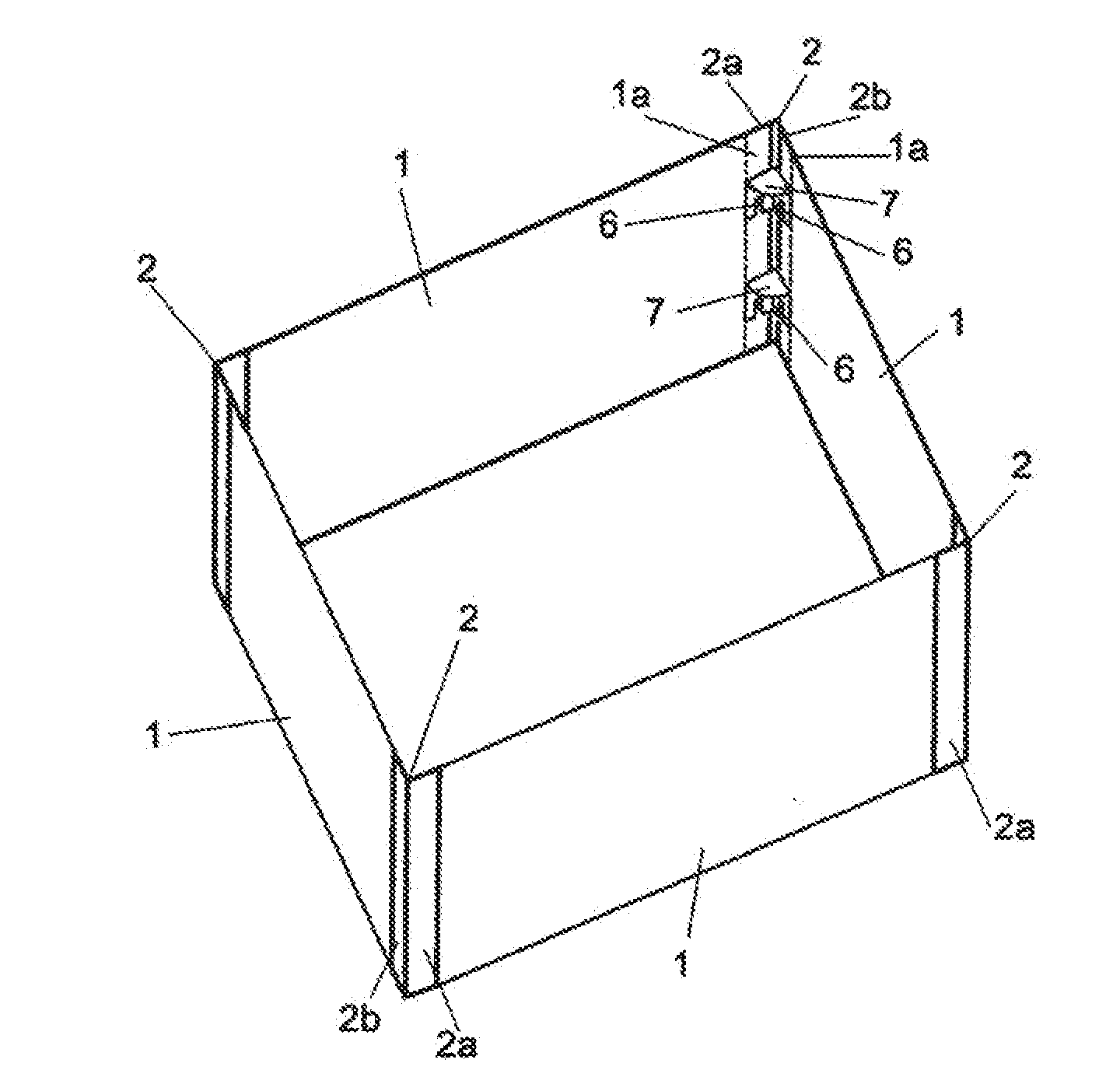
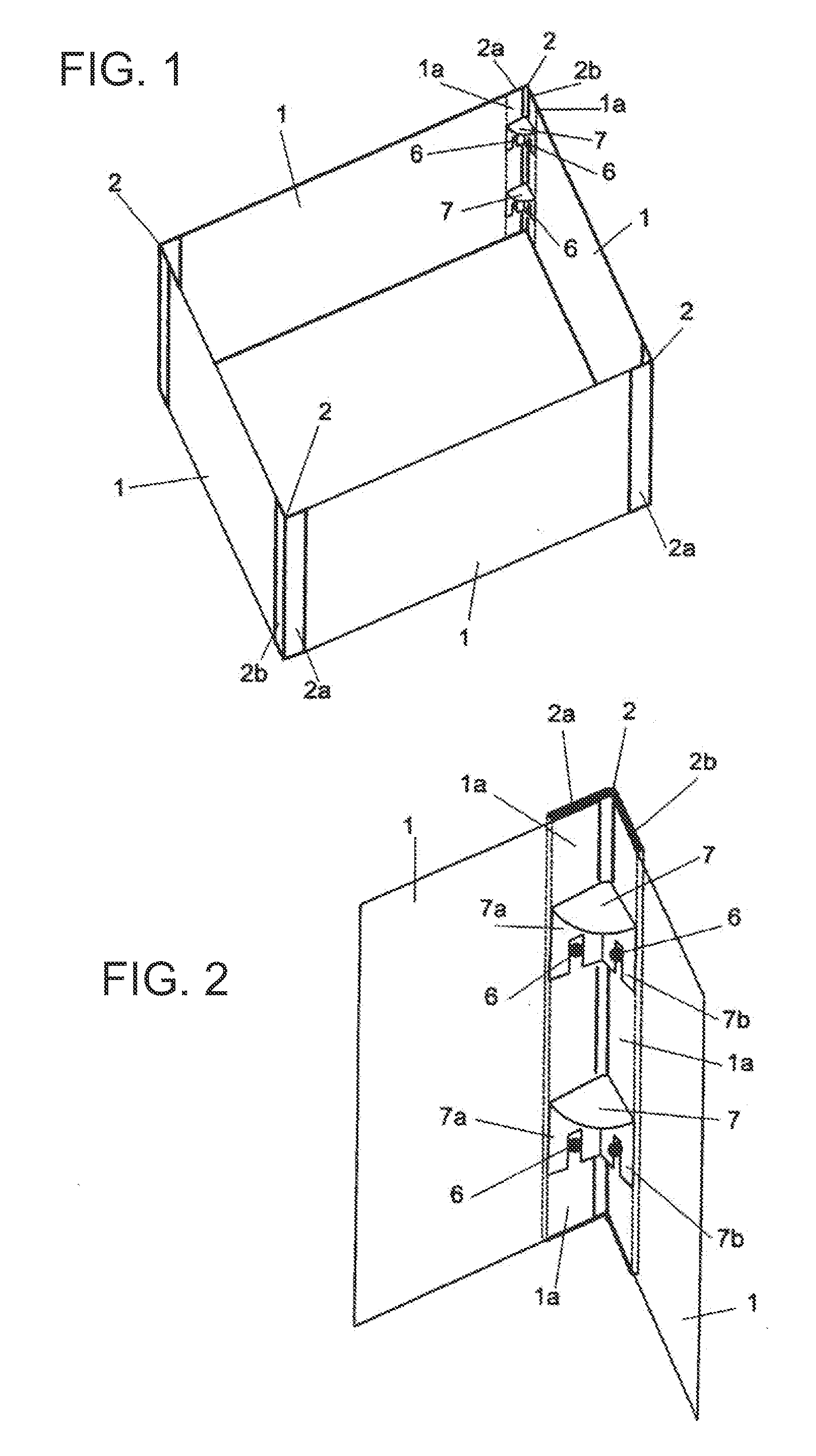
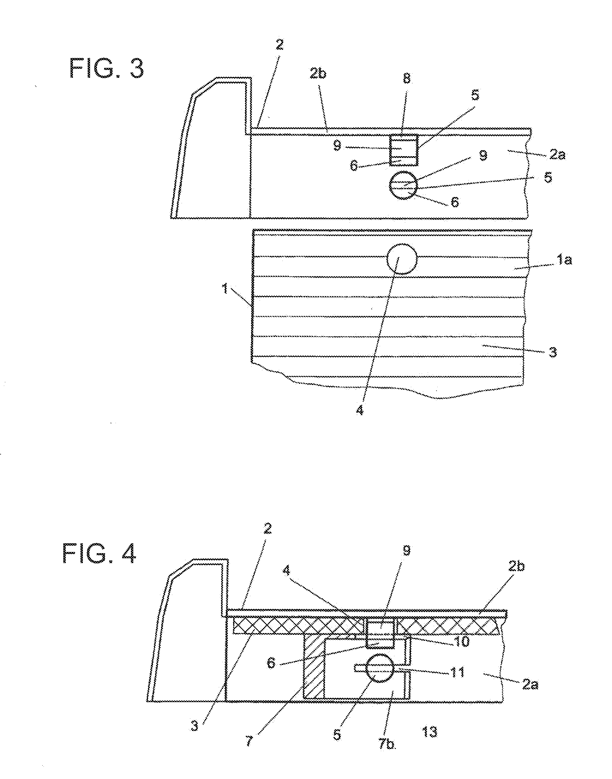
[0023]FIG. 1 shows a cold frame which has vertically arranged side wall elements 1 and vertical uprights 2. The side wall elements 1 abut by means of their lateral edge regions 1a against the lateral flanges 2a, 2b of the uprights 2. The side wall elements 1 are provided with highly transparent hollow chamber panels 3 which include, in the lateral edge regions 1a of the side wall elements 1, two through holes 4 which are separated by a relatively large spacing. The flanges 2a, 2b of the uprights 2 carry positioning pins 5 which protrude at a right angle, which are arranged in the through holes 4 in the hollow chamber panels 3, and whereof the heads 6 project beyond the hollow chamber panels 3. Clamped between the heads 6 of the positioning pins 5 and the hollow chamber panels 3 of the side wall elements 1 are clamping elements 7 which press the hollow chamber panels 3 against the flanges 2a, 2b of the uprights 2. The side wall elements 1 are connected stably to the uprights 2 by cla...


PUM


Abstract

A cold frame is formed with lateral wall elements containing transparent hollow chamber panels, and supports which are provided with lateral flanges. The lateral wall elements include lateral edge areas provided with through-passages and formed by the hollow chamber panels thereof, and rest against the flanges of the supports. The lateral wall elements are connected to the supports by clamping devices. The clamping devices include clamping elements which rest against the inner sides of the hollow cavity panels forming the edge areas of the lateral wall elements and are clamped between the hollow cavity panels and the tops of positioning bars belonging to the clamping devices. The bars protrude from the through-passages of the hollow chamber panels and they are rigidly connected to the flanges of the supports.

Description

FIELD OF THE INVENTION[0001]The invention relates to a cold frame, which has side wall elements that have highly transparent hollow chamber panels, and uprights that are provided with lateral flanges, in which the side wall elements have lateral edge regions that are formed by their hollow chamber panels, are provided with through holes, and abut against the flanges of the uprights.PRIOR ART[0002]EP 0 063 215 A2 discloses a frame-shaped container that is to be used as a cold frame. Here, the side walls, which are formed by highly transparent hollow chamber panels, are connected to the uprights by numerous pin-type connectors that on the one hand comprise individual parts that may be pushed loosely into one another and on the other pass through the through holes that lie one above the other and are provided in the edge regions of the hollow chamber panels and in the flanges of the uprights. When the container is assembled, the pin-type connectors are inserted into the through holes, ...

Claims


Application Information

Patent Timeline
IPC IPC(8): A01G9/20A01G9/14
CPCY10T403/42A01G9/20F16B2200/67
Inventor WUSTER, HEINRICH
Owner WUSTER HEINRICH
Why Eureka
Try Eureka