Injection Device

a technology of injection device and syringe, which is applied in the direction of intravenous device, medical syringe, needle infusion, etc., can solve the problems of inability to meet, picture becomes even more complex, intended action may be faulty or not occur, etc., and achieve reliable and controlled

Active Publication Date: 2011-09-01
SHL MEDICAL AG
View PDF2 Cites 28 Cited by
  • Summary
  • Abstract
  • Description
  • Claims
  • Application Information

AI Technical Summary

Benefits of technology

[0018]Because the delaying is performed by highly viscous liquid being pressed through a passage, a reliable and controlled function is obtained. The delay mechanism is preferably arranged at the front end of the plunger rod, whereby the passage could end in the interior of the plunger rod. However,

Problems solved by technology

At the same time there is a demand on robustness, repeatability and reliability regarding the function, which sometimes might be difficult to meet when dealing with complex multi functions involving many interacting components.
When there further are demands on low production costs, especially for devices that are to be used only once, the picture becomes even more complex.
There are in the patent literature numerous solutions to injection devices, the bulk of which never enter the market due to that they do not meet the demands in one way or the other.
In both cases there is a risk is that an intended action may become faulty or not occur at all.
However, since both penetration and injection are performed by a common spring acting on the plunger rod, the delay mechanism is working during the whole penetration and injection sequence whereby there is a pronounced risk that the delay function has terminated long before the end of the injection sequence is reached.
The decoupling is however delayed due to the

Method used


Image

  • Injection Device
  • Injection Device
  • Injection Device

Examples


Embodiment Construction

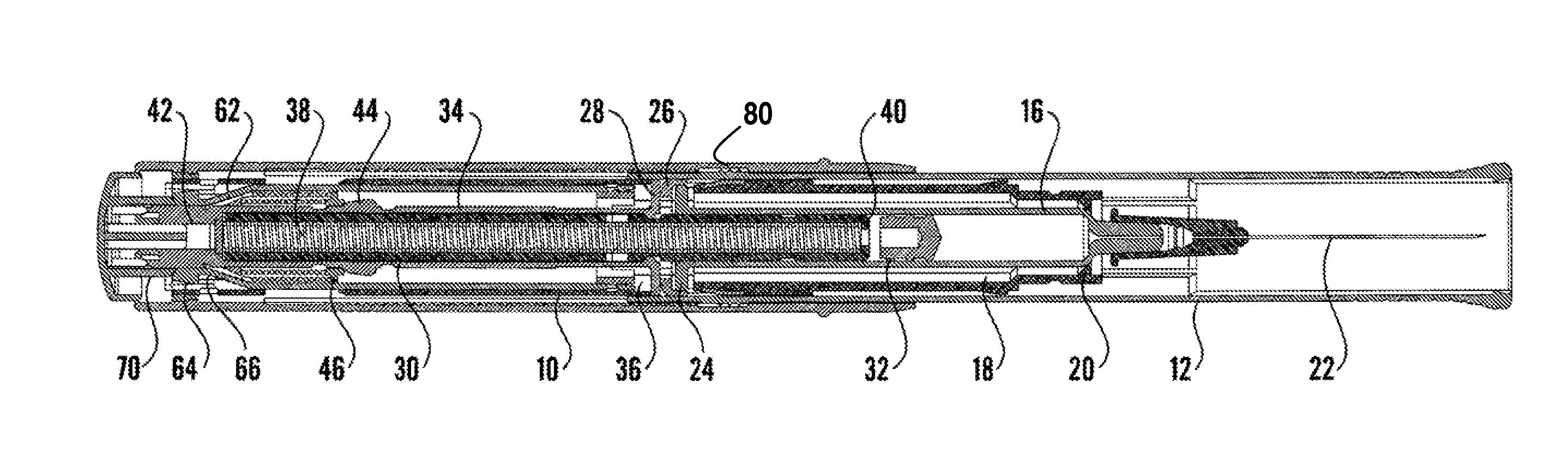
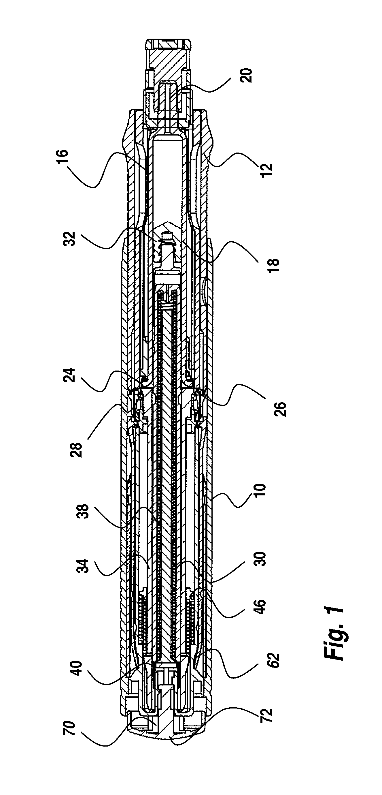
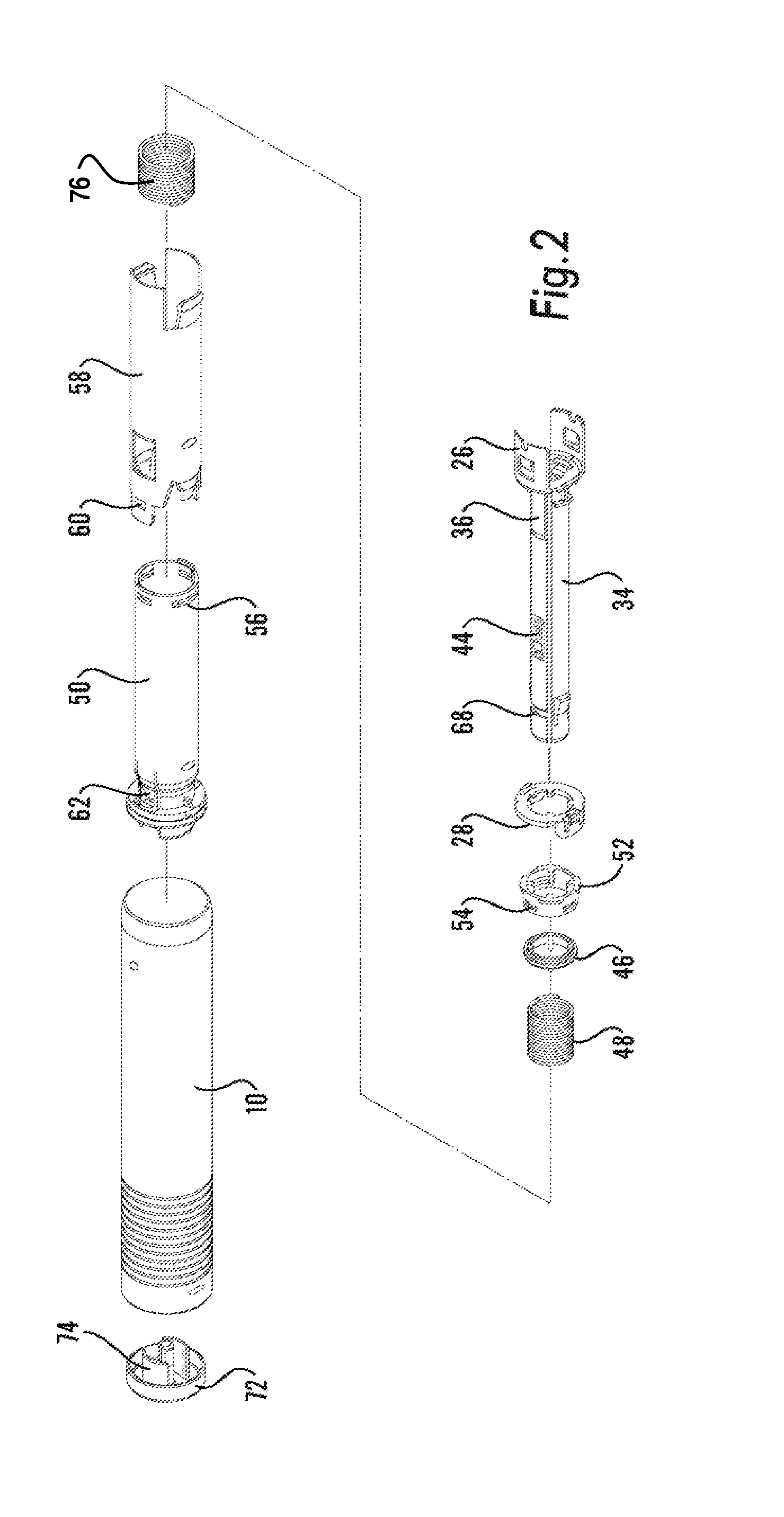
[0027]The device according to the figures comprises a generally tubular outer housing 10. In the front end of the housing, to the right in FIG. 1, a generally tubular needle shield 12 is arranged slidably in the outer housing. When in the non-extended position the needle shield is held in place by protrusions 14 on the outer surface co-operating with ledges (not shown) on the inner surface of the housing. Inside the needle shield in the front area of the device a container carrier 16 is arranged. Inside the container carrier a container 18, containing medicament, is attached. Container is to be interpreted as comprising syringes, cartridges, ampoules and the like. The front end of the container is arranged with attachment means 20 for attaching a needle 22 to the container. The rear end of the container is seated with its flange 24 in a holder 26. Adjacent the holder an injection release ring 28 is arranged, which will be described in more detail below. A plunger 30 extends into the...


PUM


Abstract

The present invention relates to an injection device comprising a medicament container (18) and a needle attached to said container, means (12,72) for automatic penetration of the needle, injection of medicament and withdrawal of the needle, comprising the steps of initiating a penetration sequence, followed by an injection sequence and followed by a withdrawal sequence, wherein a previous sequence triggers a subsequent sequence, and wherein said device further comprises a dampening means arranged and designed to dampen the movement of the injection means during the whole injection sequence.

Description

TECHNICAL FIELD[0001]The present invention relates to an injection device and in particular an injector having several automatic functions.BACKGROUND OF THE INVENTION[0002]There are many injectors on the market where the aim is to have high degrees of functionality and automatic features, such as in connection with penetration, injection, setting of dose, priming and covering of the needle after use. At the same time there is a demand on robustness, repeatability and reliability regarding the function, which sometimes might be difficult to meet when dealing with complex multi functions involving many interacting components. When there further are demands on low production costs, especially for devices that are to be used only once, the picture becomes even more complex.[0003]There are in the patent literature numerous solutions to injection devices, the bulk of which never enter the market due to that they do not meet the demands in one way or the other. There is therefore a continu...

Claims


Application Information

Patent Timeline
IPC IPC(8): A61M5/32
CPCA61M5/2033A61M5/3232A61M5/46A61M2005/3143A61M2005/208A61M2005/2086A61M2005/206
Inventor GUILLERMO, CARLOS
Owner SHL MEDICAL AG
Why Eureka
Try Eureka