Fixing unit and image forming apparatus

a technology of fixing unit and fixing plate, which is applied in the field of fixing plate and image forming apparatus, can solve the problems of recording medium sometimes experiencing curling, back curling, and greatly affecting the fixing performance of the fixing pla

Inactive Publication Date: 2011-09-22
RICOH KK
View PDF15 Cites 97 Cited by
  • Summary
  • Abstract
  • Description
  • Claims
  • Application Information

AI Technical Summary

Benefits of technology

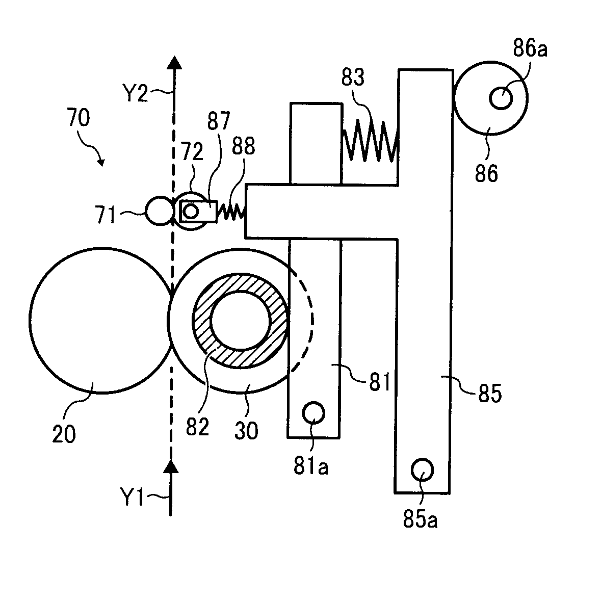
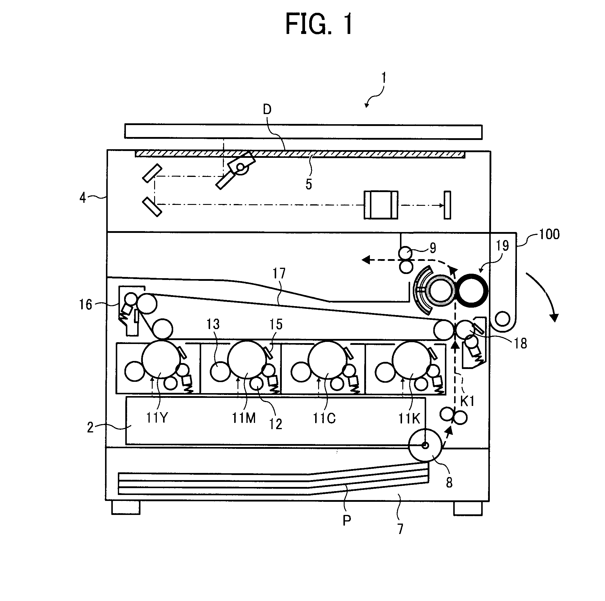
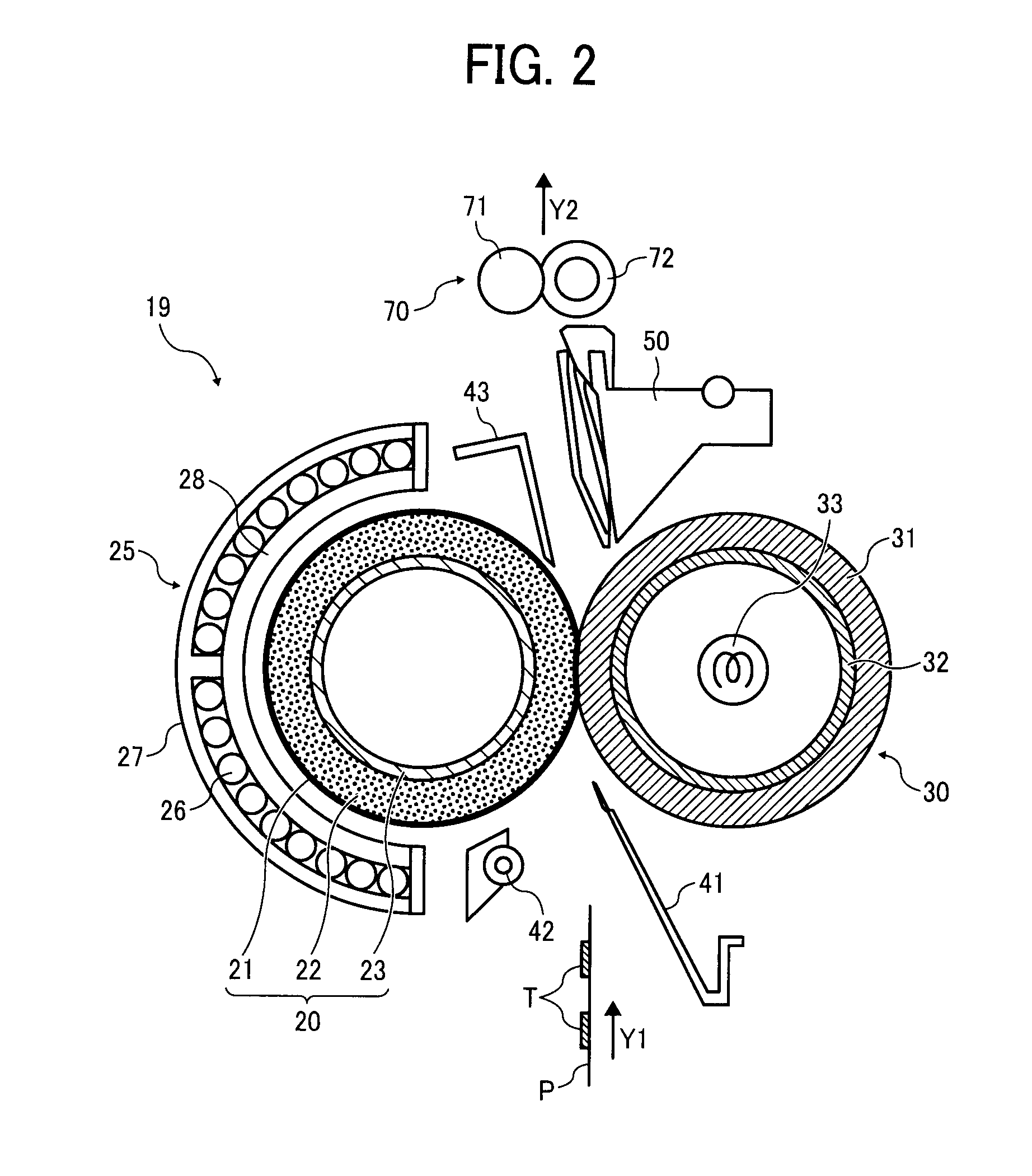
[0009]In one aspect of the present a fixing unit is devised. The fixing unit includes a fixing member to fuse a toner image on a recording medium by heating and melting the toner image on the recording medium; a pressure member to press against the fixing member, to define a first nip, as a fixing nip, between the fixing member and the pressure member through which the recording medium is transported; a shifting unit to move the pressure member relative to the fixing member to increase or decrease a pressure of the first nip; a curling correction unit disposed downstream from the first nip in a transport direction of the recording medium that imparts a second curling direction to the recording medium, opposite of a first curling direction of the recording medium exiting the first nip; and a variable setting unit operatively connected to the curling correction unit to variably set an amount of the second curling direction to be applied to the recording medium by the curling correction unit depending on the first nip pressure increased or decreased by the shifting unit.

Problems solved by technology

Furthermore, it is known that the size or extent of the nip width and the nip pressure at the fixing nip in the fixing unit greatly affects fixing performance.
Further, because the recording medium receives relatively greater pressure and heat at the fixing nip position, after the recording medium exits the fixing nip, it is known that the recording medium sometimes experiences curling such as back curling.
However, the amount of curling of the recording medium may fluctuate because the nip pressure varies in response to the recording medium.
In such a case, jamming of recording medium (or sheet jamming) may occur along a transportation route through which the recording medium is transported after the fixing nip, thus degrading image quality.

Method used


Image

  • Fixing unit and image forming apparatus
  • Fixing unit and image forming apparatus
  • Fixing unit and image forming apparatus

Examples


Embodiment Construction

[0018]A description is now given of exemplary embodiments of the present invention. It should be noted that although such terms as first, second, etc. may be used herein to describe various elements, components, regions, layers and / or sections, it should be understood that such elements, components, regions, layers and / or sections are not limited thereby because such terms are relative, that is, used only to distinguish one element, component, region, layer or section from another region, layer or section. Thus, for example, a first element, component, region, layer or section discussed below could be termed a second element, component, region, layer or section without departing from the teachings of the present invention.

[0019]In addition, it should be noted that the terminology used herein is for the purpose of describing particular embodiments only and is not intended to be limiting of the present invention. Thus, for example, as used herein, the singular forms “a”, “an” and “the...


PUM


Abstract

A fixing unit includes a fixing member to fuse a toner image on a recording medium on the recording medium; a pressure member to press against the fixing member to define a first nip between the fixing member and the pressure member through which the recording medium is transported; a shifting unit to move the pressure member relative to the fixing member to increase or decrease a pressure of the first nip; a curling correction unit disposed downstream from the first nip in a transport direction of the recording medium that imparts a second curling direction to the recording medium; and a variable setting unit operatively connected to the curling correction unit to variably set an amount of the second curling direction to the recording medium by the curling correction unit depending on the first nip pressure increased or decreased by the shifting unit.

Description

CROSS-REFERENCE TO RELATED APPLICATIONS[0001]This application claims priority to Japanese Patent Application No. 2010-058951, filed on Mar. 16, 2010 in the Japan Patent Office, which is incorporated by reference herein in its entirety.BACKGROUND OF THE INVENTION[0002]1. Field of the Invention[0003]The present invention relates to an image forming apparatus such as a copier, a printer, a facsimile machine, or a multi-functional apparatus having some combination of these functions, and a fixing unit disposed in the image forming apparatus, and more particularly, to an image forming apparatus having a fixing unit to increase and decrease a nip pressure between a fixing member and a pressure member.[0004]2. Description of the Background Art[0005]Conventionally, image forming apparatuses such as copiers and printers employ a fixing unit having a fixing member and a pressure member to conduct a fixing process, in which a fixing nip is set between the fixing member and the pressure member ...

Claims


Application Information

Patent Timeline
Patent Type & Authority Applications(United States)
IPC IPC(8): G03G15/20
CPCG03G15/6576G03G2215/20G03G2215/00662
Inventor OGAWA, TADASHIEHARA, MASANAOUENO, SATOSHISEO, HIROSHIIMADA, TAKAHIROHASE, TAKAMASA
Owner RICOH KK
Why Eureka
Try Eureka