
Wireless communication system and wireless communication method

a wireless communication and wireless communication technology, applied in the field of wireless communication systems and wireless communication methods, can solve problems such as the starvation of limited frequency resources, and achieve the effect of not degrading the data transmitting efficiency

Active Publication Date: 2011-10-06
NIPPON TELEGRAPH & TELEPHONE CORP
View PDF2 Cites 17 Cited by
  • Summary
  • Abstract
  • Description
  • Claims
  • Application Information

AI Technical Summary

Benefits of technology

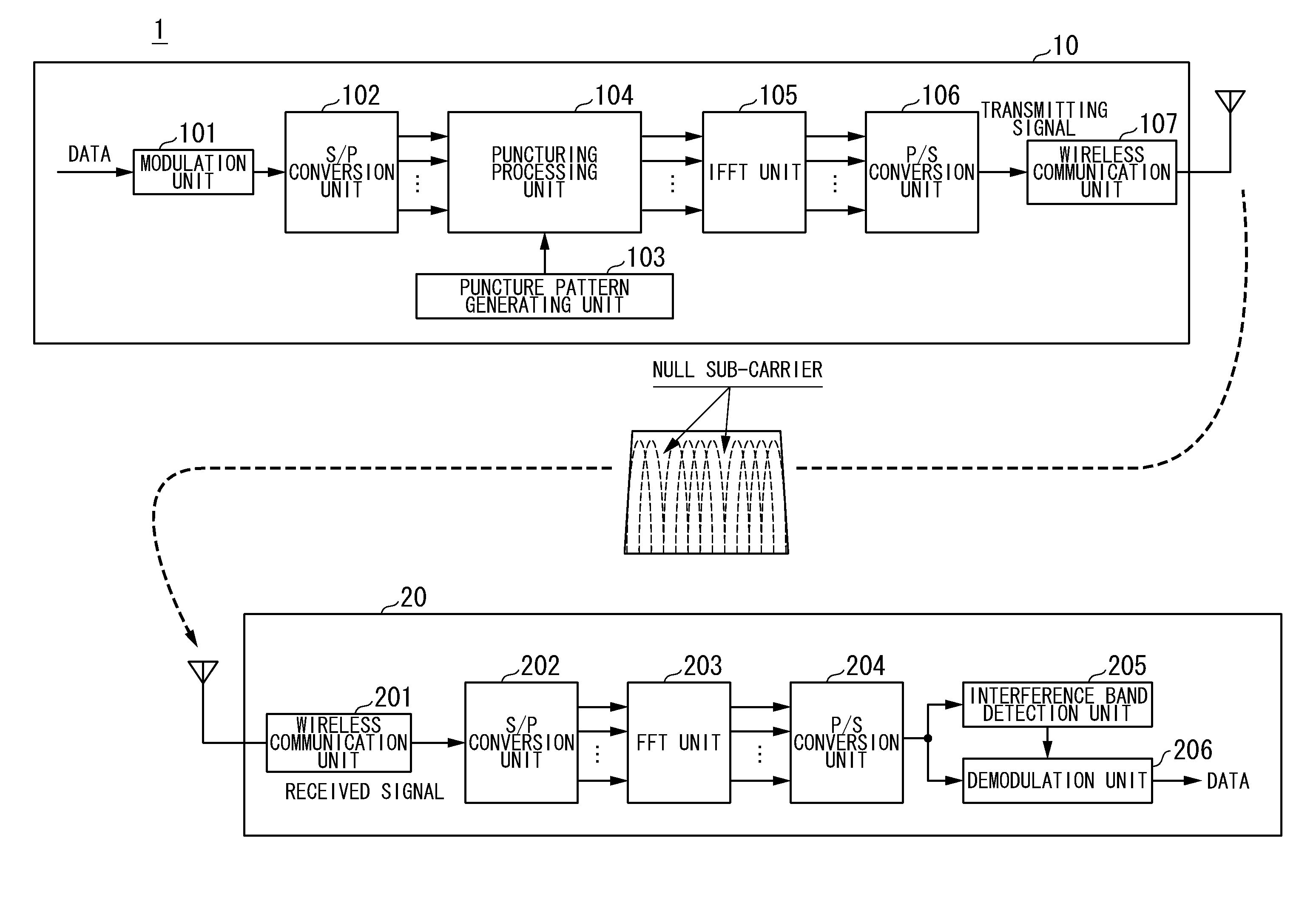
[0026]In this invention, after implementation of error correction coding on transmitting data, a transmitter device transmits a null sub-carrier having zero amplitude representing a part of a sub-carrier for transmitting data with error correcting codes. A receiver device detects an interference signal, representing a signal having a null sub-carrier frequency band, from received signals while performing error correction decoding so as to decode transmitted data. Since this invention is able to generate a null sub-carrier without the addition of more data, exclusively used for generating a null sub-carrier, to transmitting data, it is possible to detect an interference signal without degrading the data transmitting efficiency.

Problems solved by technology

Recently, starvation of limited frequency resources has been a serious problem in the field of wireless communication; hence, it is expected to improve frequency availability.

Method used


Image

  • Wireless communication system and wireless communication method
  • Wireless communication system and wireless communication method
  • Wireless communication system and wireless communication method

Examples


first embodiment

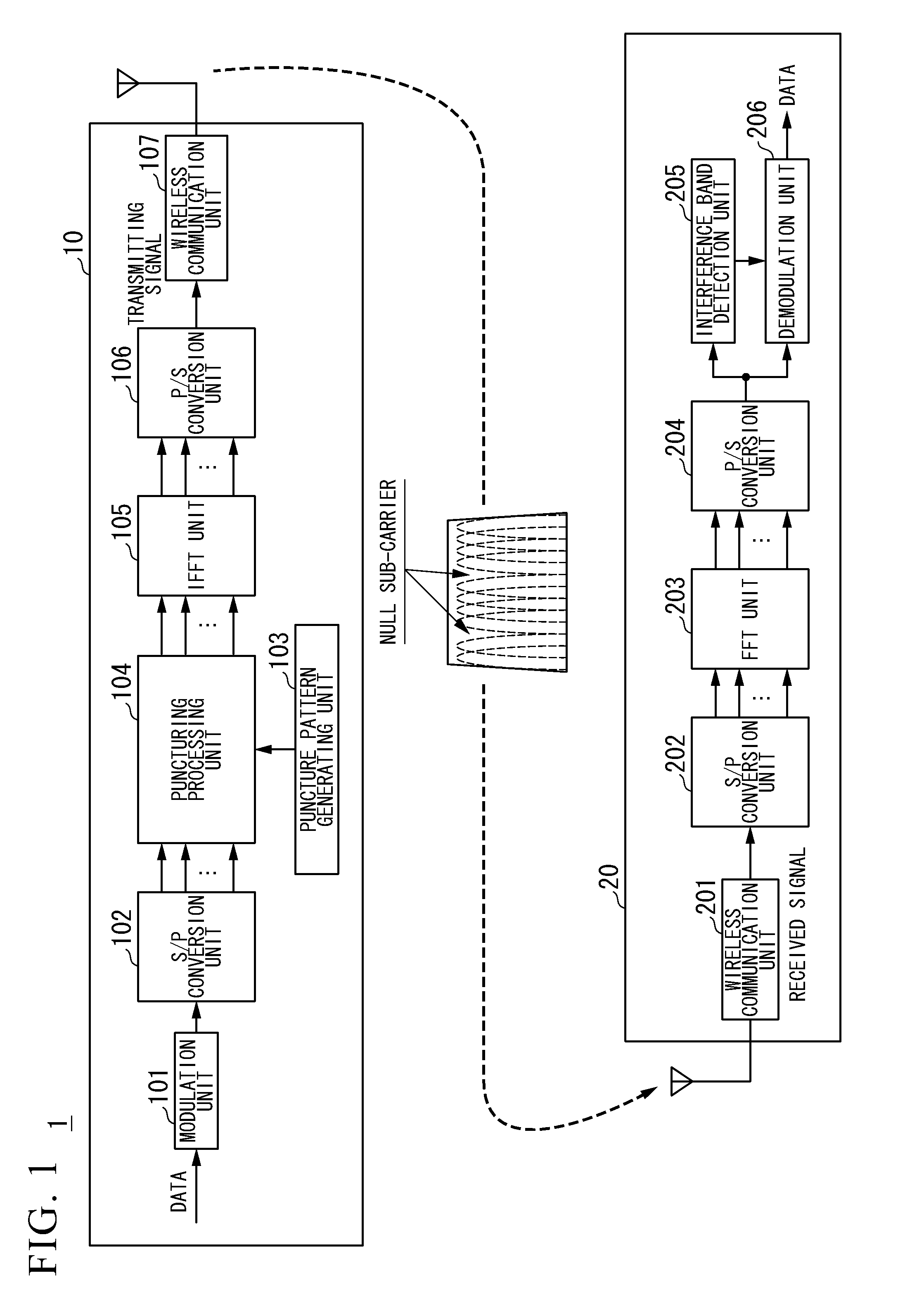
[0048]FIG. 1 is a block diagram showing the constitution of a wireless communication system 1 including a transmitter device 10 and a receiver device 20. The wireless communication system 1 is constituted of the transmitter device 10 for transmitting data and the receiver device 20 for receiving data from the transmitter device 10.

[0049]The wireless communication system 1 of this embodiment adopts an OFDM (Orthogonal Frequency Division Multiplexing) method achieving multicarrier communication; hence, the following description refers to an application of a superposed multicarrier transmission method.

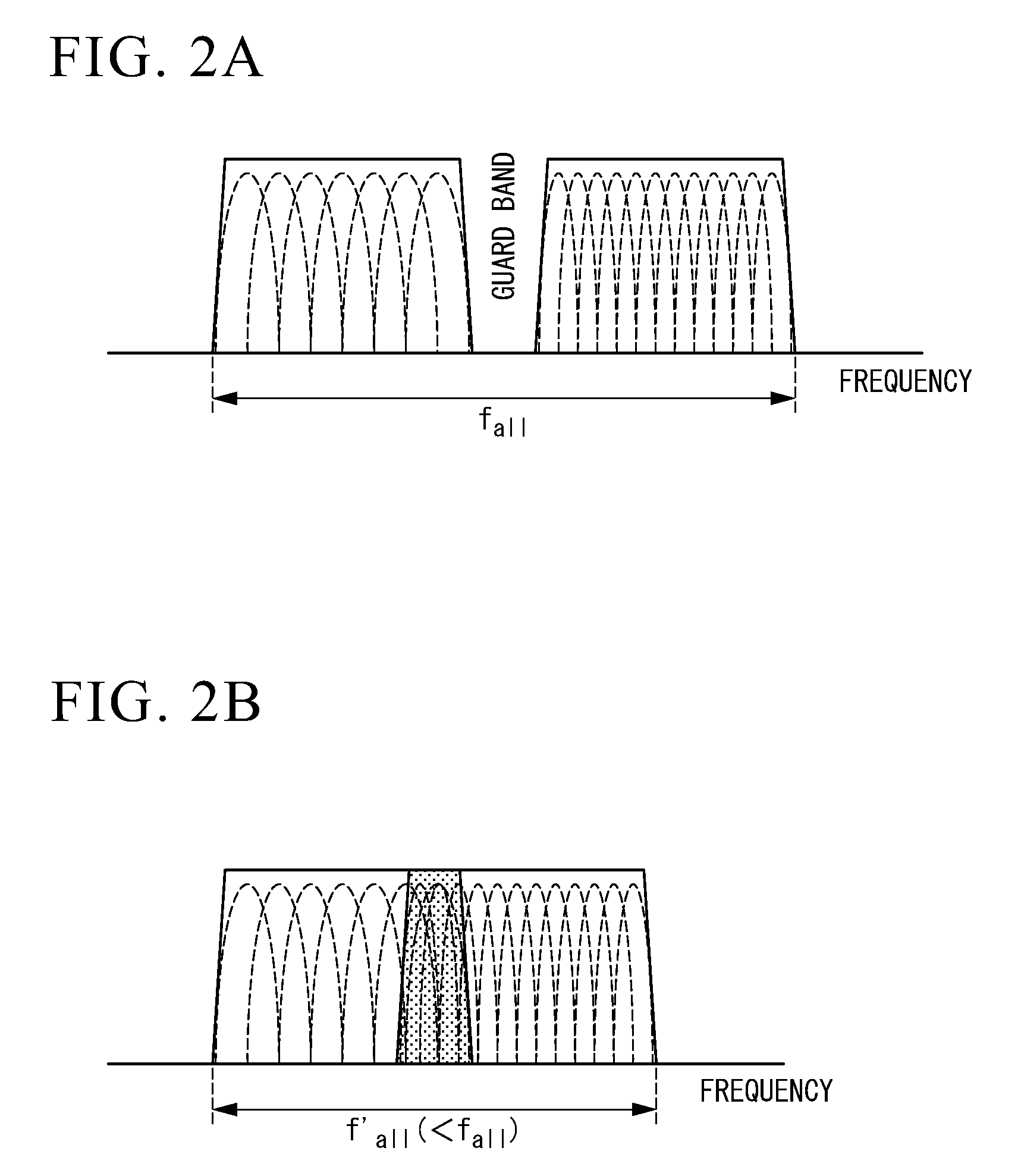
[0050]The superposed multicarrier transmission method is a name of one technology for improving frequency availability. FIGS. 2A and 2B are illustrations for explaining the superposed multicarrier transmission method. Generally speaking, as shown in FIG. 2A, wireless communication system performing communication using a plurality of nearby frequency bands introduces a guard band between a...

second embodiment

[0080]FIG. 6 is a block diagram showing the overall constitution of a wireless communication system 3 including a transmitter device 12 and a receiver device 22 according to a second embodiment. The wireless communication system 3 is constituted of the transmitter device 12 for transmitting data and the receiver device 22 for receiving data from the transmitter device 12. Similar to the wireless communication system 1 of the first embodiment, the wireless communication system 3 adopts an OFDM method demonstrating multicarrier communication; hence, the following description is made with reference to a superposed multicarrier transmission method.

[0081]The transmitter device 12 includes the modulation unit 101, the S / P conversion unit 102, the puncturing processing unit 104, the IFFT unit 105, the P / S conversion unit 106, a wireless communication unit 127, a timer unit 123, and a puncture pattern generating unit 124. The transmitter device 12 differs from the transmitter device 10 of t...

third embodiment

Variation of Third Embodiment

[0152]FIGS. 16 and 17 are block diagrams showing the functional constitutions of the transmitter device 50 and the receiver device 60 included in the wireless communication system 5 according to a variation of the third embodiment. The transmitter device 50 can be redesigned to further include an interference band information signal reception unit 508. The receiver device 60 can be redesigned to further include an interference band information signal transmission unit 610. In this case, the transmitter device 50 receives interference band information transmitted by the receiver device 60 so as to operate based on the interference band information. Hereinafter, the transmitter device 50 and the receiver device 60 having the above constitutions will be described.

[0153]The interference band information signal transmission unit 610 generates interference band information based on the detection result of the interference signal detection unit 609. The interfe...


PUM


Abstract

In a wireless communication system including a transmitter device and a receiver device used for transmission of wireless signals having a plurality of sub-carriers, the transmitter device performs error correction coding on transmitting data and selects at least one of the plurality of sub-carriers used for transmission of error-correction coded data as a null sub-carrier having zero amplitude, thus transmitting the error-correction coded data, whilst the receiver device receives signals having the plurality of sub-carriers from the transmitter device so as to retrieve original transmitted data by implementing error correction decoding on received signals, thus determining whether an interference wave occurs in the sub-carrier upon detecting reception power exceeding a predetermined threshold in the sub-carrier serving as the null sub-carrier.

Description

TECHNICAL FIELD[0001]This invention relates to wireless communication systems and wireless communication methods.[0002]This application claims priority on Japanese Patent Application No. 2008-324412 filed on Dec. 19, 2008 and Japanese Patent Application No. 2009-49785 filed on Mar. 3, 2009, the entire contents of which are incorporated herein by reference.BACKGROUND ART[0003]Recently, starvation of limited frequency resources has been a serious problem in the field of wireless communication; hence, it is expected to improve frequency availability. Frequency sharing wireless communication may serve as a technology for improving frequency availability. FIG. 18 is a conceptual illustration showing the overall system constitution including two wireless LANs (Local Area Network) using different frequency channels, which is one example of a combination of wireless communication systems sharing frequency bands.[0004]The illustrated wireless communication system includes wireless LAN base s...

Claims


Application Information

Patent Timeline
Patent Type & Authority Applications(United States)
IPC IPC(8): H04B15/00
CPCH04J11/0066H04L1/0003H04L1/0026H04L1/0065H04L5/0007H04L27/2611H04L5/0062H04L5/0073H04L25/0228H04L27/0006H04L27/2601H04L5/0048H04L27/26H03M13/03H04L1/00
Inventor MASHINO, JUNSUGIYAMA, TAKATOSHI
Owner NIPPON TELEGRAPH & TELEPHONE CORP
Learn More