
Handle structure

a technology of handle and handle, applied in the field of handle structures, can solve problems such as exacerbated problems

Inactive Publication Date: 2011-10-13
MEADWESTVACO PACKAGING SYST LLC
View PDF9 Cites 18 Cited by
  • Summary
  • Abstract
  • Description
  • Claims
  • Application Information

AI Technical Summary

Benefits of technology

[0017]A second aspect of the present invention provides a blank for forming a carton having a handle structure, which blank comprises panels for forming opposed side walls and opposed top and bottom wall, to form a tubular structure, and panels to form end closure panels of that tubular structure, which end closure panels comprise a first and a second side end panels, each comprising a free edge furthest from a fold line hinging that end panel to the panels for forming the carton, within which free edge is defined a cutout, defined within which cutout is a reinforcing flap comprising a first portion and a second portion connected to one another by a narrow portion defined by an indent in a free edge of the reinforcing flap, and being hinged to the side end panel so as to allow only partial folding of the first portion out of the plane of the handle opening, whereby to at least partially direct stresses placed upon the first portion, around the indent, and into portions of the side end panel to which the second portion is hinged.

Problems solved by technology

When packages are so lifted the weight of those packages is transferred to one or more edges of the handle openings and this load may in some cases lead to tearing.
This problem is exacerbated if the material of the packaging is to some degree moistened as moisture weakens the materials such as paperboard of which packaging is often manufactured.

Method used


Image

  • Handle structure
  • Handle structure
  • Handle structure

Examples


Embodiment Construction

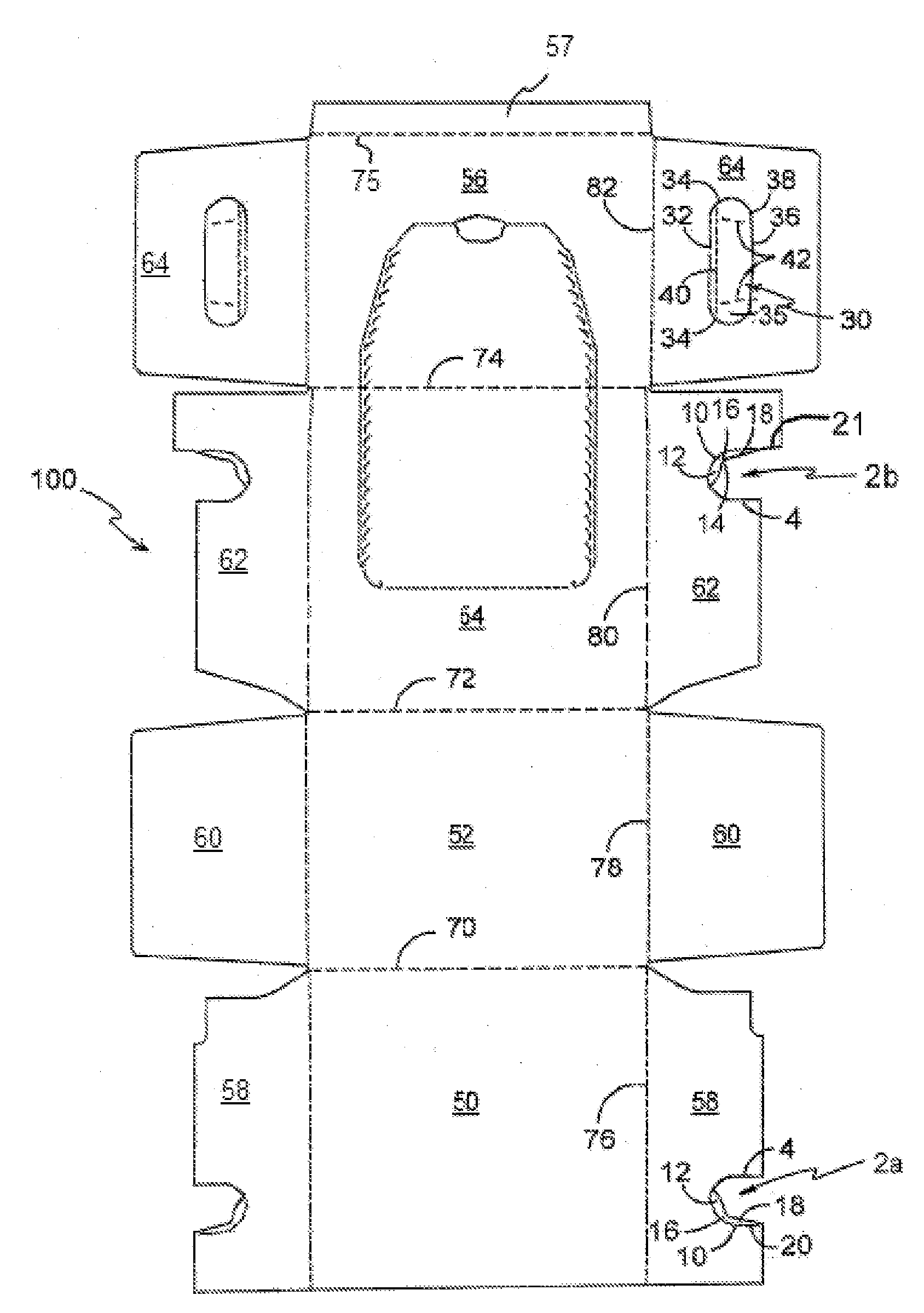
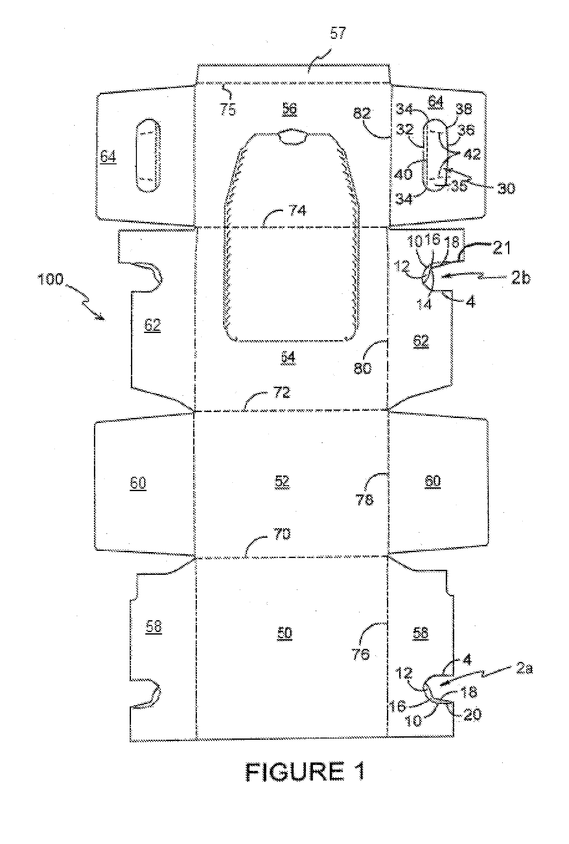
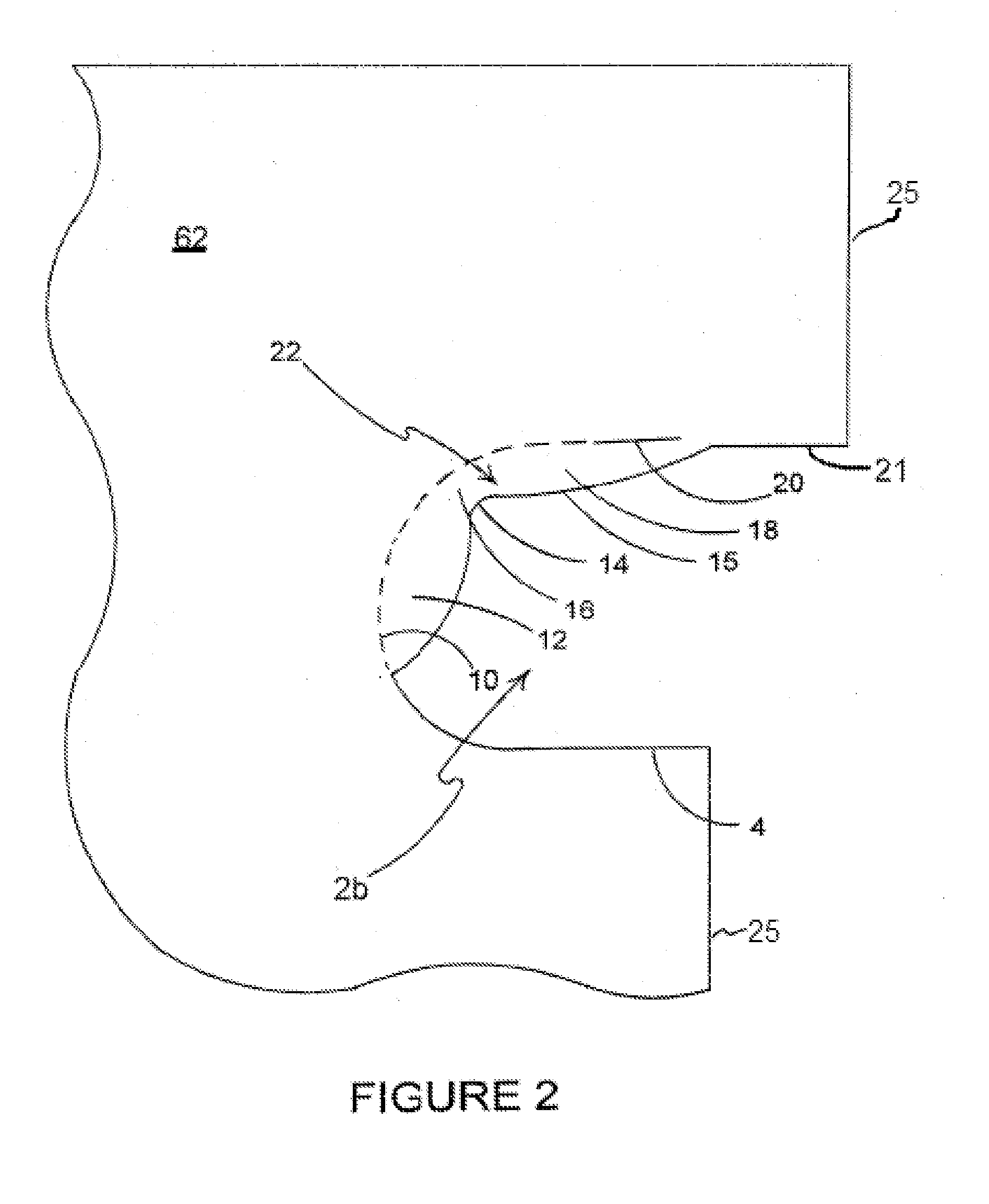
[0028]The present invention relates, in a preferred embodiment, to a handle structure 1 comprising a handle opening 3 formed from a first handle cutout 2a, and a second handle cutout 2b (shown best in FIG. 2) defined in adjacent terminal edges of two adjacent handle panels 58, 62, and defined within each of which are reinforcing flaps 22.

[0029]The handle cutouts 2a, 2b in each of the handle panels 58, 62 are substantially the mirror image of the other, but differ from one another in the manner set out below.

[0030]The first handle cutout 2a in handle panel 58 is defined partially by upper and lower cut lines 20, 4. The upper cut lines 20 extends from a point inwardly offset from the terminal edge 25 of the handle panel 58, whilst the lower cut line 4 extend inwardly from the terminal edge 25 itself. A score line 10 connects adjacent terminal ends of those cut lines 4, 20.

[0031]The upper cut line 20 is linear and co-axial with a linear first portion of the score line 10, which score l...


PUM


Abstract

A handle structure includes a reinforcing flap struck from a handle panel to define at least a part of a handle opening for insertion of a user's hand. The reinforcing flap comprises a first portion and a second portion connected to one another by a narrow portion defined by an indent in a free edge of the reinforcing flap.

Description

CROSS REFERENCE TO RELATED APPLICATION[0001]This application claims priority to U.S. Provisional Application No. 61 / 250,668, filed Oct. 12, 2009, the entirety of which is incorporated herein by reference.FIELD OF THE INVENTION[0002]The present invention relates generally though not specifically to handle structures for use in cartons for packaging articles. More specifically, though still not exclusively, the invention relates to handle structures comprising foldable flaps that hinge upon insertion of a user's fingers into the handle structure so as to resist tearing.BACKGROUND OF THE INVENTION[0003]It is known in the art to provide handle openings in packaging such as cartons so as to allow users to insert one or more fingers to allow lifting of those packages. When packages are so lifted the weight of those packages is transferred to one or more edges of the handle openings and this load may in some cases lead to tearing. This problem is exacerbated if the material of the packagin...

Claims


Application Information

Patent Timeline
IPC IPC(8): B65D5/46
CPCB65D5/542B65D5/4608
Inventor HOLLEY, JR., JOHN M.
Owner MEADWESTVACO PACKAGING SYST LLC
Learn More