Supercharge Your Innovation With Domain-Expert AI Agents!

Press in place seal

a technology of a seal and a press, applied in the direction of engine seals, engine components, mechanical devices, etc., can solve the problems of seal failure, leakage, seal failure,

Inactive Publication Date: 2011-12-15
CATERPILLAR INC
View PDF13 Cites 2 Cited by
  • Summary
  • Abstract
  • Description
  • Claims
  • Application Information

AI Technical Summary

Benefits of technology

The patent describes a PIP seal used in a channel with a flat surface. The seal has a cross section that is trapezoidal in shape when compressed. The seal has a top portion with a first bead and a second bead, and a bottom portion with a third bead and a fourth bead. The seal is subjected to a pressure of about 27.6 MPa and has a highest strain experienced at the bottom portion. The seal occupies a volume of the channel that is between 80% and 90% of the channel's volume. The seal has a seal height and a seal width that are proportional to the channel's width. The seal has a strain field that extends through it at an angle between 10 degrees and 80 degrees. The patent also describes an assembly that includes the PIP seal and the channel.

Problems solved by technology

However, at higher pressures, such as 27.6 MPa or greater, such spaced flexible projections may affect the contact pressure between the seal and the channel causing leakage to occur.
Also, such intermittent projections may act as a stress raiser causing the seal to fail.
These seals may also fail because of movement in response to an applied pressure.
Such movement may cause the seal to roll or twist, allowing fluid to move around the seal and leak.
Additionally, known seals may begin to fail by extruding through the interface between the two structures when in use at higher pressures because the highest strain experienced by the seal during use is found at the surface of the seal proximate the interface of the two structures.

Method used


Image

  • Press in place seal
  • Press in place seal
  • Press in place seal

Examples


Embodiment Construction

[0032]As used herein, about means the numerical value plus or minus ten percent.

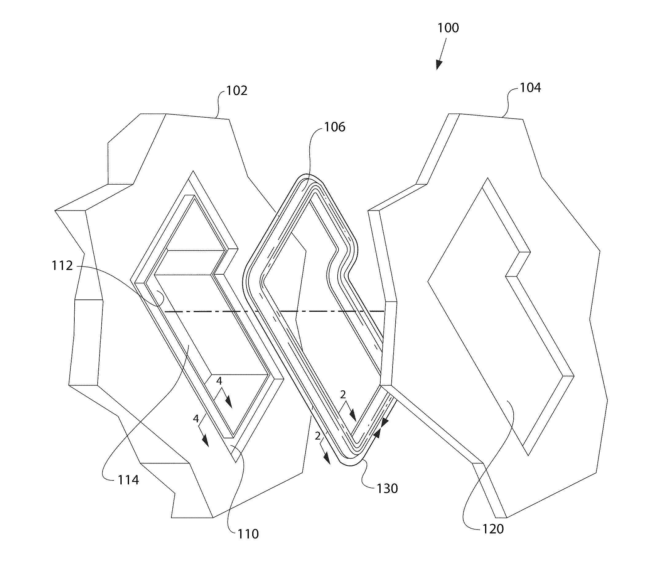
[0033]Referring to FIG. 1, an exploded perspective view illustrates an example of an embodiment of the invention. As shown, an assembly 100 includes a first structure 102, a second structure 104, and a PIP seal 106. The first and second structures 102, 104 are the components of a machine that require a fluid seal at an interface between the first and second structures 102, 104. The first structure 102 includes a channel 110 having a substantially rectangular cross section. The channel 110 surrounds an edge 112 of an aperture 114. The second structure 104 includes a mating aperture 120 and covers the channel 110 when assembled.

[0034]Fluid may pass through the aperture 114 and the mating aperture 120. The pressure of the fluid may pulse to or remain at high pressures for a period of time. The pressure of the fluid is applied to the PIP seal 106 and the interface between the first and second structures 102,...


PUM


Abstract

A press-in-place or “PIP” seal has a length and a cross section. The cross section, when in an uncompressed state, includes a top portion that includes a first bead and a second bead. The top portion has a seal width. The cross section further includes a bottom portion having a third bead and a fourth bead. The bottom portion has a narrow width that is narrower than the seal width. A first side surface connects the third bead with the first bead and a second side surface connecting the fourth bead with the second bead.

Description

TECHNICAL FIELD[0001]This invention relates generally to a press in place of “PIP” seal for sealing an interface between two surfaces.BACKGROUND[0002]Seals are used in numerous applications to prevent a fluid from leaking between two structures. Many seals include spaced flexible projections that retain the seal in a channel of a structure during assembly. However, at higher pressures, such as 27.6 MPa or greater, such spaced flexible projections may affect the contact pressure between the seal and the channel causing leakage to occur. For example, in U.S. Pat. No. 5,002,290 a seal is provided to provide fluid tightness but includes such spaced flexible projections.[0003]Also, such intermittent projections may act as a stress raiser causing the seal to fail.[0004]These seals may also fail because of movement in response to an applied pressure. Such movement may cause the seal to roll or twist, allowing fluid to move around the seal and leak.[0005]Additionally, known seals may begin ...

Claims


Application Information

Patent Timeline
Patent Type & Authority Applications(United States)
IPC IPC(8): F16J15/02
CPCF16J15/062F16J15/024
Inventor STICKLING, CHRISTOPHER J.
Owner CATERPILLAR INC
Features
  • R&D
  • Intellectual Property
  • Life Sciences
  • Materials
  • Tech Scout
  • Unparalleled Data Quality
  • Higher Quality Content
  • 60% Fewer Hallucinations
Learn More