

Chain saw
- Summary
- Abstract
- Description
- Claims
- Application Information
AI Technical Summary
Benefits of technology
Problems solved by technology
Method used
Image

Examples
Embodiment Construction
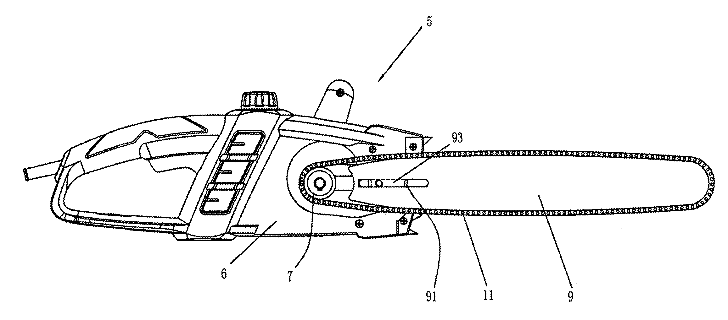
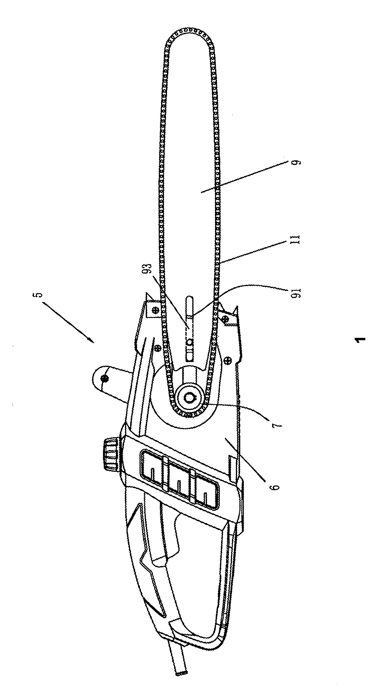
As shown in FIG. 1, in one embodiment of the present invention, it involves a chain saw 5, which comprises a housing 6; a sprocket wheel 7 provided in the housing for driving a saw chain 11; of which, this sprocket wheel 7 is driven by a power unit through a driver (not shown in the FIG. 1), and this power unit can be a motor or an engine; this chain saw 5 also includes a chain guide 9, one end of which is in the housing 6, and the other end of which extends out longitudinally from the housing 6; the saw chain 11 is cased around the sprocket wheel 7 and chain guide 9, and it can be guided along the edge of the chain guide 9 in cycles. In order to adjust the tension of the saw chain 11, this chain guide 9 can move corresponding to the housing 6 along the longitudinal extension direction of this chain guide 9, so that the distance between the chain guide 9 and the sprocket wheel 7 can be adjusted, and the saw chain 11 can be tensioned or loosed.
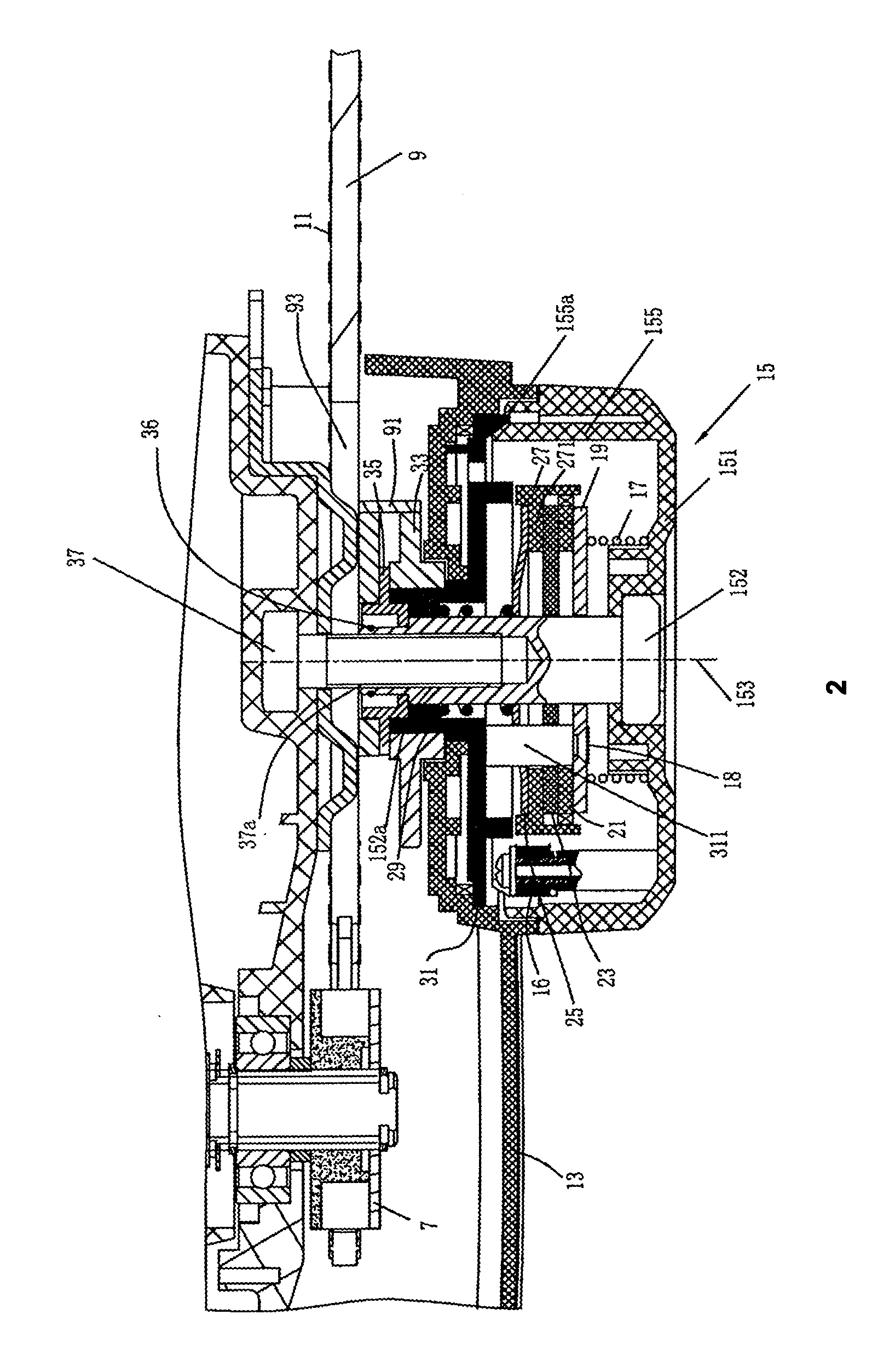
As shown in FIG. 2 and FIG. 3, in order ...
PUM
| Property | Measurement | Unit |
|---|---|---|
| Force | aaaaa | aaaaa |
| Pressure | aaaaa | aaaaa |
| Elasticity | aaaaa | aaaaa |
Abstract
Description
Claims
Application Information