
Chain saw

a chain saw and chain guide technology, applied in the field of chain saws, can solve the problems of only solving the problem, increasing the danger of the chain jumping from the chain guide, and the tensioning process is relatively complicated, so as to prevent the saw chain from falling off and jumping off, and the tensioning device is stable and stable. anti-abrasion and labor-saving

Active Publication Date: 2018-01-30
POSITEC POWER TOOLS (SUZHOU) CO LTD
View PDF28 Cites 2 Cited by
  • Summary
  • Abstract
  • Description
  • Claims
  • Application Information

AI Technical Summary

Benefits of technology

The solution provides a stable and efficient saw chain tensioning system that maintains consistent tension without user-dependent adjustments, preventing chain loosening and ensuring safe operation.

Problems solved by technology

This chain tensioning process is relatively complicated, and the fixation of the chain guide tends to loosen, which may cause the saw chain to be loose and increases the danger of the chain to jump from the chain guide.
Therefore, this problem can only be solved by frequently conducting follow-up tensioning to the saw chain.
However, during the tensioning process, it requires separate operations to the internal and external hand wheels, which are complicated and the human-machine function is weak.
It has convenient operation and strong human-machine function, but the detent overload clutch tends to be worn and the structure is not stable enough.
In addition, during backward rotation of the rotating device to exchange the chain, efforts need to be made to overcome the clamping resistance between the detent elements of the detent overload clutch, and the operation is not easy.

Method used


Image

  • Chain saw
  • Chain saw
  • Chain saw

Examples


Embodiment Construction

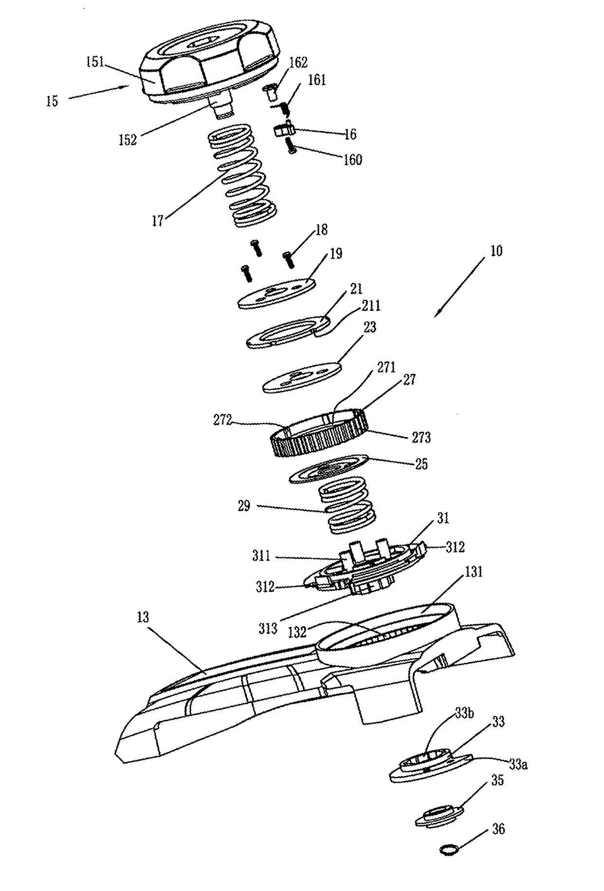
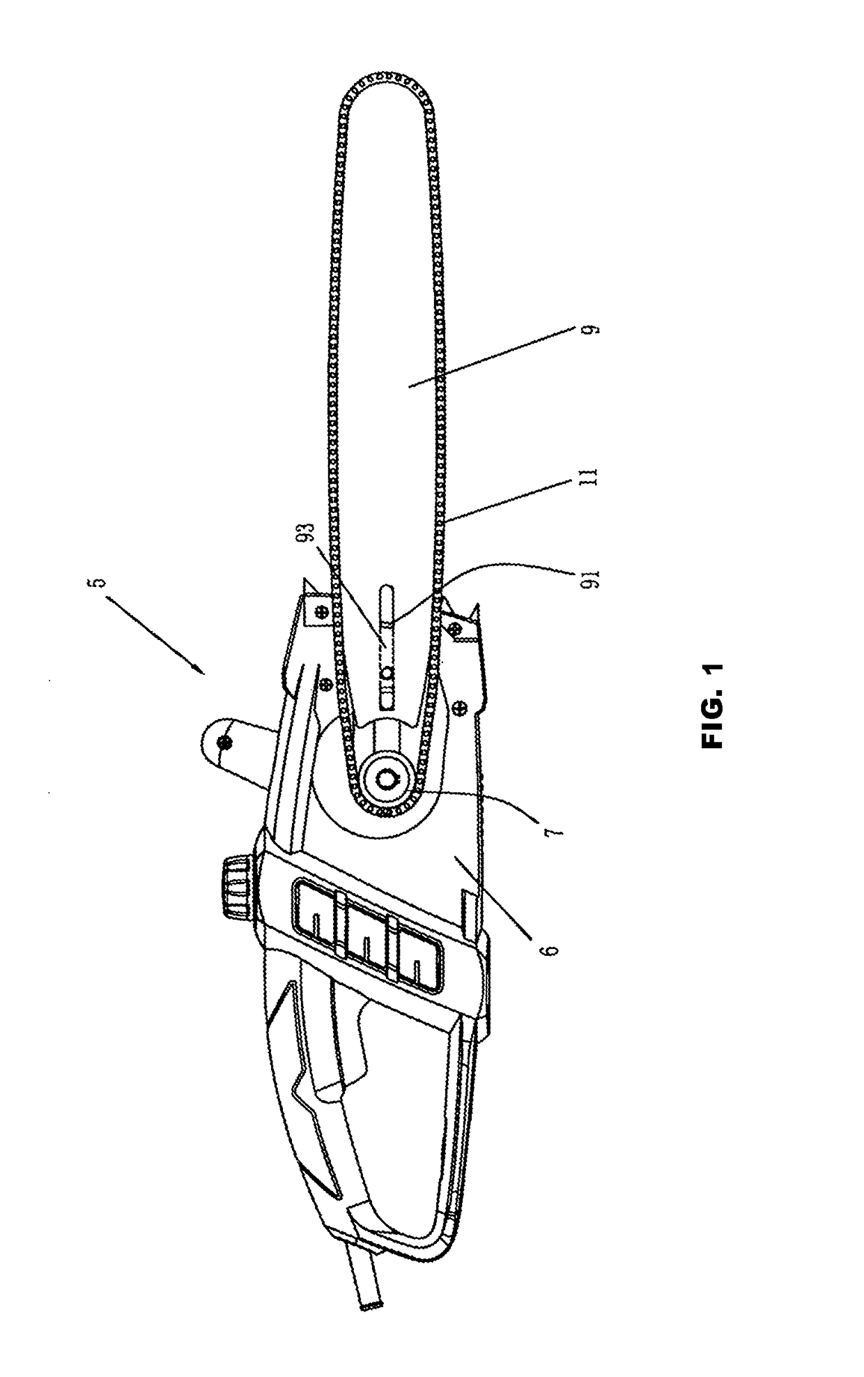
[0026]As shown in FIG. 1, in one embodiment of the present invention, it involves a chain saw 5, which comprises a housing 6; a sprocket wheel 7 provided in the housing 6 for driving a saw chain 11; of which, this sprocket wheel 7 is driven by a power unit through a driver (not shown in the FIG. 1), and this power unit can be a motor or an engine; this chain saw 5 also includes a chain guide 9, one end of which is in the housing 6, and the other end of which extends out longitudinally from the housing 6; the saw chain 11 is cased around the sprocket wheel 7 and chain guide 9, and it can be guided along the edge of the chain guide 9 in cycles. In order to adjust the tension of the saw chain 11, this chain guide 9 can move corresponding to the housing 6 along the longitudinal extension direction of this chain guide 9, so that the distance between the chain guide 9 and the sprocket wheel 7 can be adjusted, and the saw chain 11 can be tensioned or loosed.

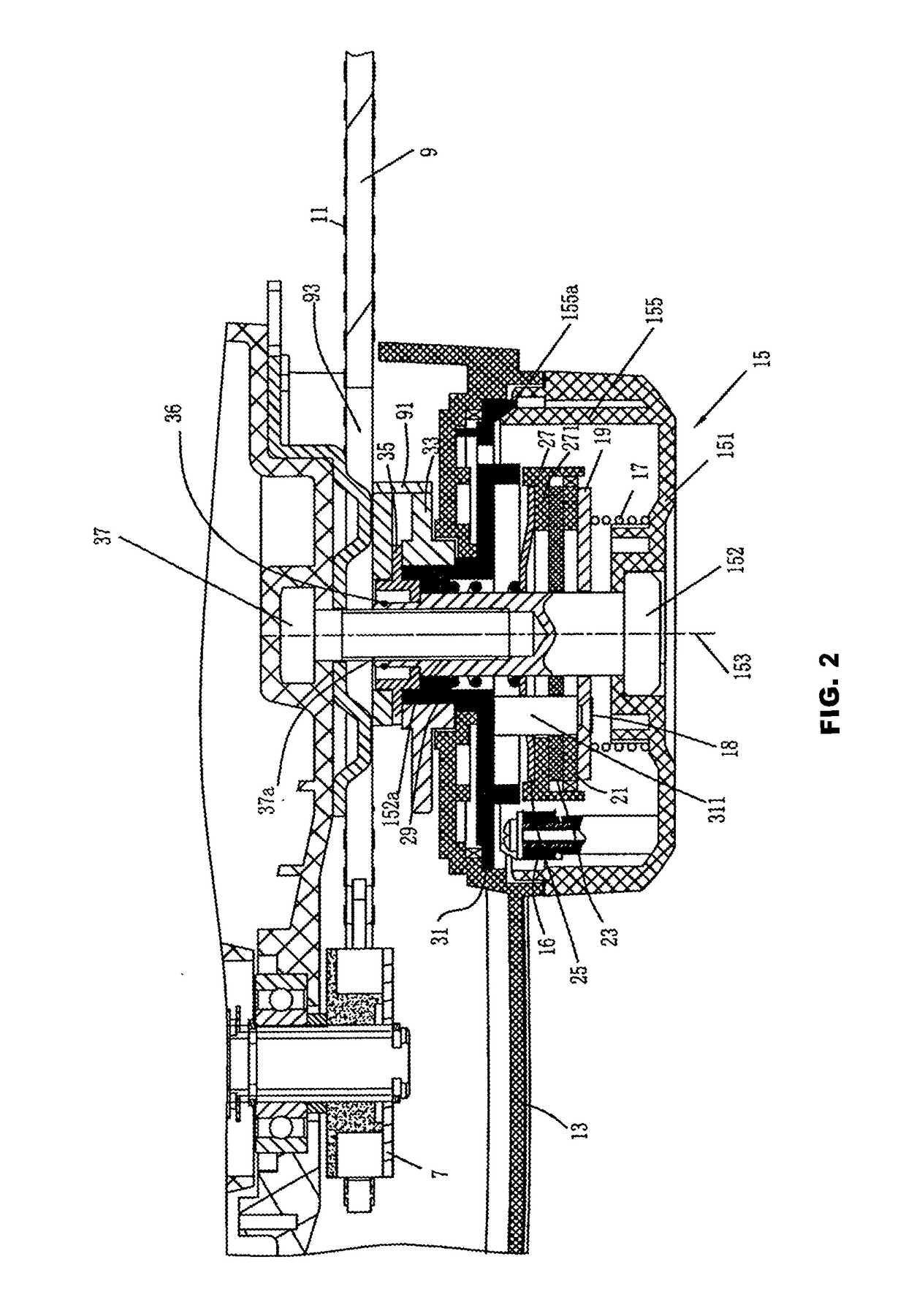
[0027]As shown in FIG. 2 and FIG...


PUM

PropertyMeasurementUnit
friction pressureaaaaaaaaaa
elasticaaaaaaaaaa
friction forceaaaaaaaaaa

Abstract

A chain saw includes a housing, a sprocket wheel which is provided in the housing for driving a saw chain, and a chain guide for guiding the movement of the saw chain. The chain guide extends out longitudinally from the housing and is movable longitudinally relative to the housing. The chain saw includes a chain tensioning device. The chain tensioning device comprises a driven member arranged on the chain guide and a driving member which drives the driven member to move the chain guide longitudinally and a rotating device rotating the driving member. A stepless clutch device is arranged between the rotating device and the driving member. The chain tensioning device presses the chain guide while it tensioning the saw chain. Thus it prevents effectively the chain guide from loosing after the saw chain is tensioned. The operation of the chain tensioning device is labor-saving. The chain tensioning device has a stable structure and it is hard to be worn.

Description

TECHNICAL FIELD[0001]The present invention generally relates to a chain saw, and more particularly to a chain tensioning device for a chain saw.BACKGROUND OF THE INVENTION[0002]A PCT patent application WO9833631, which is published on Aug. 6, 1998 discloses a chain saw with a chain tensioning device, in which, the chain guide of the chain saw is fixed between two clamping plates and then fixed on the housing with them, and it can move longitudinally corresponding to the housing. Through a hole of the eccentric wheel and a rectangular hole on the housing, a bolt is tightened on the clamping plates which are guided and can move longitudinally on the housing, and its bolt head fixes the eccentric wheel on the housing. In order to tension the chain, first loosen the bolt and rotate the eccentric wheel, so that the bolt and clamping plates will move toward the direction of the chain guide top; when the chain has reached the expected tension, stop rotating the eccentric wheel, and then ti...

Claims


Application Information

Patent Timeline
Patent Type & Authority Patents(United States)
IPC IPC(8): B27B17/14
CPCB27B17/14
Inventor YU, XIDENG, WEICHEN, XIULIAN
Owner POSITEC POWER TOOLS (SUZHOU) CO LTD
Learn More