Robot calibration system and calibrating method thereof

a robot and calibration system technology, applied in the field of robot calibration system and calibrating method thereof, can solve the problems of difficult or impossible to accurately observe the movement of the robot, manual calibration is time-consuming, costly and inconsistent,

Inactive Publication Date: 2011-12-29
HONG FU JIN PRECISION IND (SHENZHEN) CO LTD +1
View PDF0 Cites 55 Cited by
  • Summary
  • Abstract
  • Description
  • Claims
  • Application Information

AI Technical Summary

Problems solved by technology

Robotic position calibration is a problem found in automation systems using robots.
Furthermore, manual calibration is time-co

Method used


Image

  • Robot calibration system and calibrating method thereof
  • Robot calibration system and calibrating method thereof
  • Robot calibration system and calibrating method thereof

Examples


Embodiment Construction

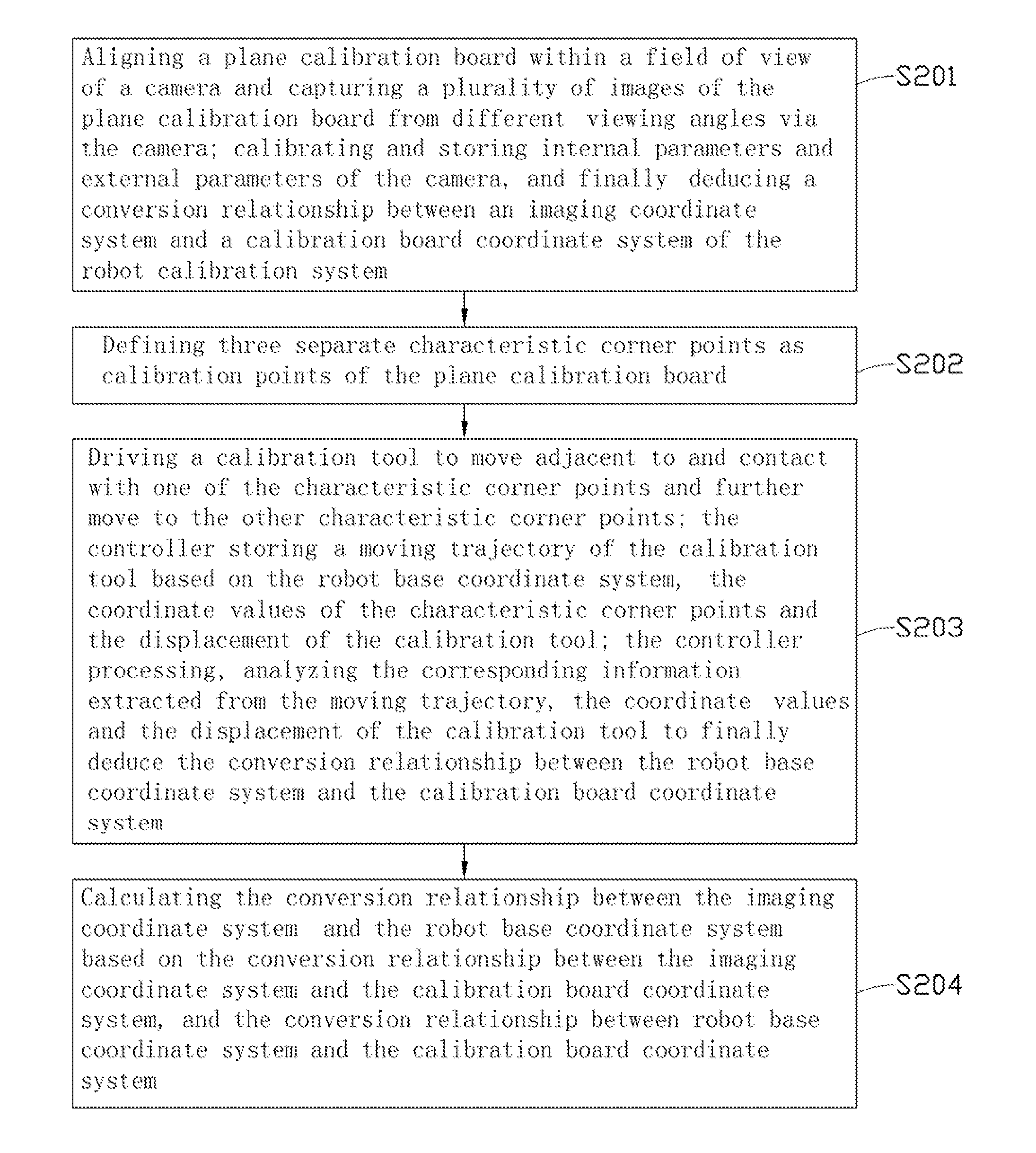
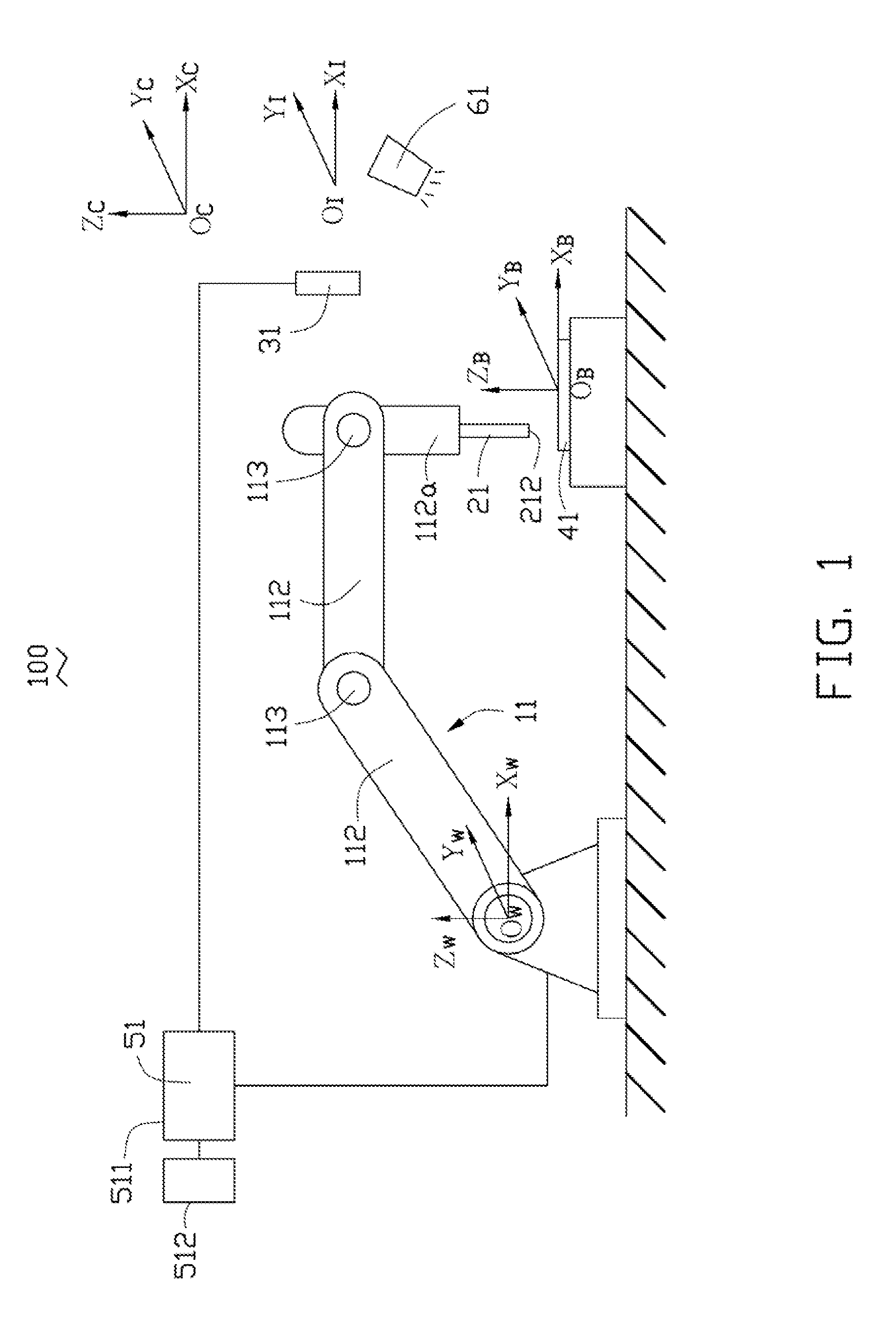
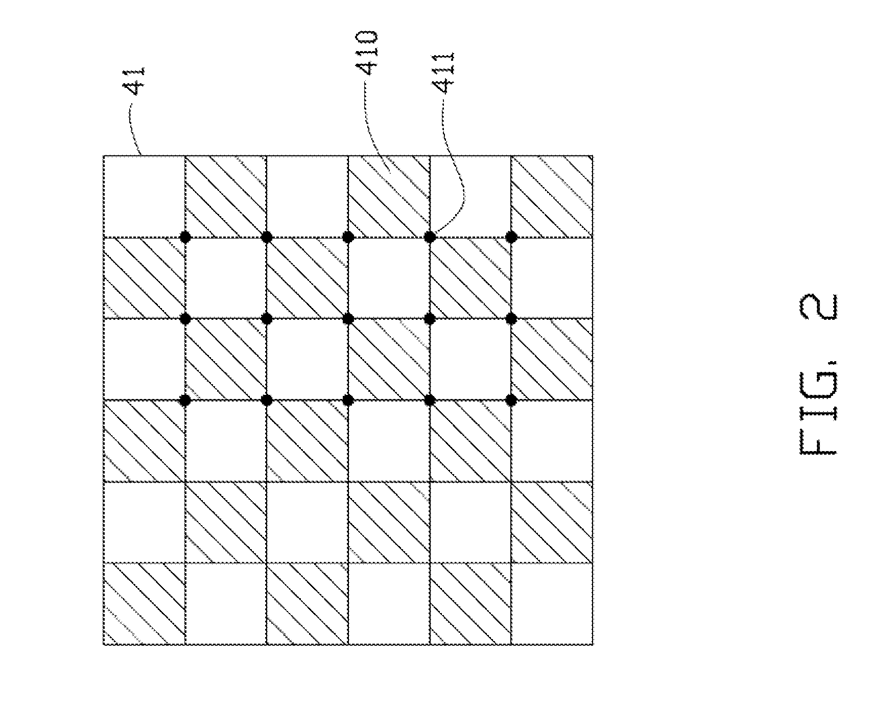
[0011]Referring to FIG. 1, a robot calibration system 100 includes a robot 11, a calibration tool 21, a camera 31, a plane calibration board 41 located within a field angle of the camera 31, a controller 51 and a light source 61. The robot calibration system 100 defines a robot base coordinate system {W}, a camera coordinate system {C}, an imaging coordinate system {I}, and a calibration board coordinate system {B}.

[0012]The robot base coordinate system {W} is established based on the robot 11 and consists of an origin OW, a first coordinate axis OWXW, a second coordinate axis OWYW perpendicular to the first coordinate axis OWXW, and a third coordinate axis OWZW perpendicular to the first coordinate axis OWXW and the second coordinate axis OWYW. The camera coordinate system {C} is established based on the camera 31 and consists of an origin OC, a first coordinate axis OCXC, a second coordinate axis OCYC perpendicular to the first coordinate axis OCXC, and a third coordinate axis OCZ...


PUM


Abstract

A robot calibration system includes a robot, a calibration tool, a plane calibration board, a camera, and a controller. The calibration tool is assembled to the robot and is controlled by the robot to move along a preset trajectory. The plane calibration board is located under the calibration tool and has a plurality of characteristic corner points on one surface thereof. The camera is configured for capturing an image of the plane calibration board. The controller electrically connects with the robot and the camera respectively, the controller predefines a preset control program for controlling the robot and the camera to operate, and the controller is configured for calibrating the robot. The disclosure also discloses a method for calibrating a robot for use with a robot calibration system.

Description

BACKGROUND[0001]1. Technical Field[0002]The present disclosure generally relates to the field of robotic position calibration, and particularly, to a robot calibration system and a calibrating method thereof.[0003]2. Description of Related Art[0004]Robotic position calibration is a problem found in automation systems using robots. The most common calibration of the desired positions for robots is done manually by an expert in the field. However, manual calibration is dependent upon the visual acuity of the skilled expert. Furthermore, manual calibration is time-consuming, costly and inconsistent. Sometimes tool geometry makes accurate observations of robot motions difficult or impossible.[0005]Therefore, there is room for improvement within the art.BRIEF DESCRIPTION OF THE DRAWINGS[0006]Many aspects of the disclosure can be better understood with reference to the following drawings. The components in the drawings are not necessarily drawn to scale, the emphasis instead being placed ...

Claims


Application Information

Patent Timeline
IPC IPC(8): B25J13/08B25J9/02
CPCB25J9/1692
Inventor HSU, YUAN-CHEZHANG, DU-XUEWEI, SHUI-PING
Owner HONG FU JIN PRECISION IND (SHENZHEN) CO LTD
Why Eureka
Try Eureka