Supercharge Your Innovation With Domain-Expert AI Agents!

Operation detection apparatus

Active Publication Date: 2012-01-19
YAMAHA CORP
View PDF15 Cites 9 Cited by
  • Summary
  • Abstract
  • Description
  • Claims
  • Application Information

AI Technical Summary

Benefits of technology

[0004]In view of the foregoing, it is an object of the present invention to provide a technique for allowing a user to instantly ascertain tone materials, allocated to individual operating surfaces, during a performance of an electronic musical instrument.
[0006]Because the see-through portion for allowing a region below the sensor section to be partly seen therethrough is provided in association with the hitting portion, the user can hit the hitting portions while viewing a display presented under the hitting portion of the pad and seen through the see-through portion. Thus, by a mark or image indicative of a tone material allocated to the hitting portion being displayed under the hitting portion, the user is allowed to execute an intuitive performance.

Problems solved by technology

However, with the electronic musical instrument disclosed in the relevant prior art literature, the user cannot ascertain types of the tone materials, allocated to the individual operating surfaces, while performing.

Method used


Image

  • Operation detection apparatus
  • Operation detection apparatus
  • Operation detection apparatus

Examples


first embodiment

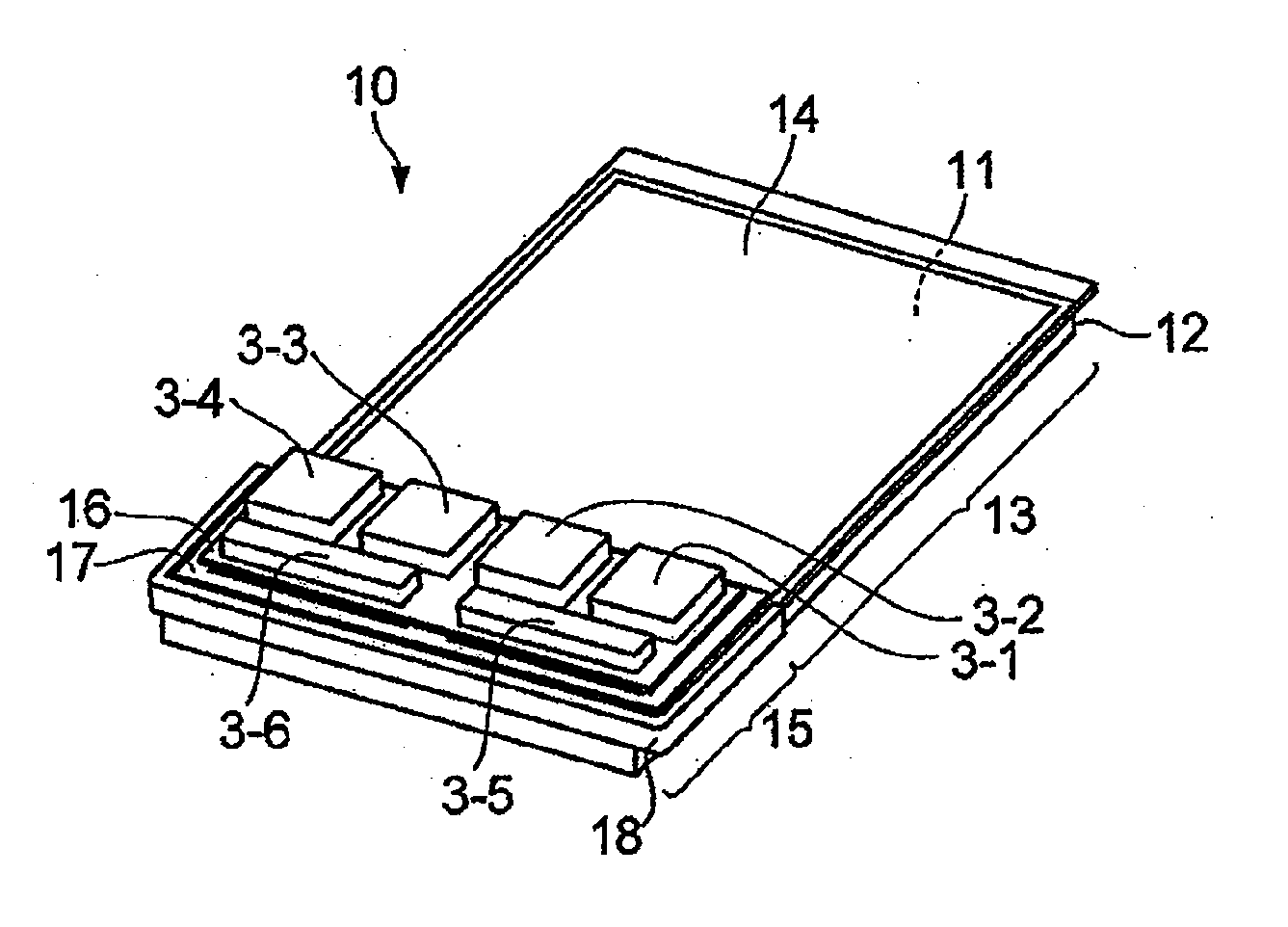
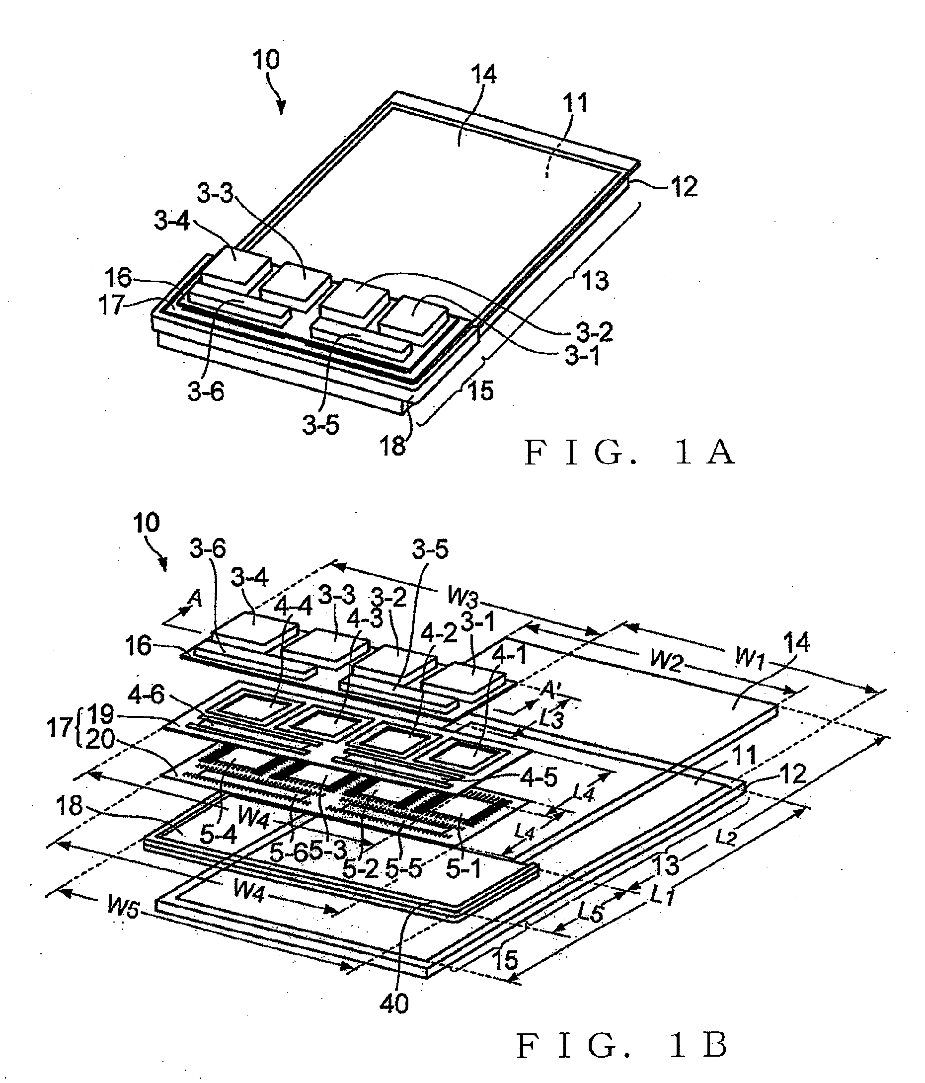
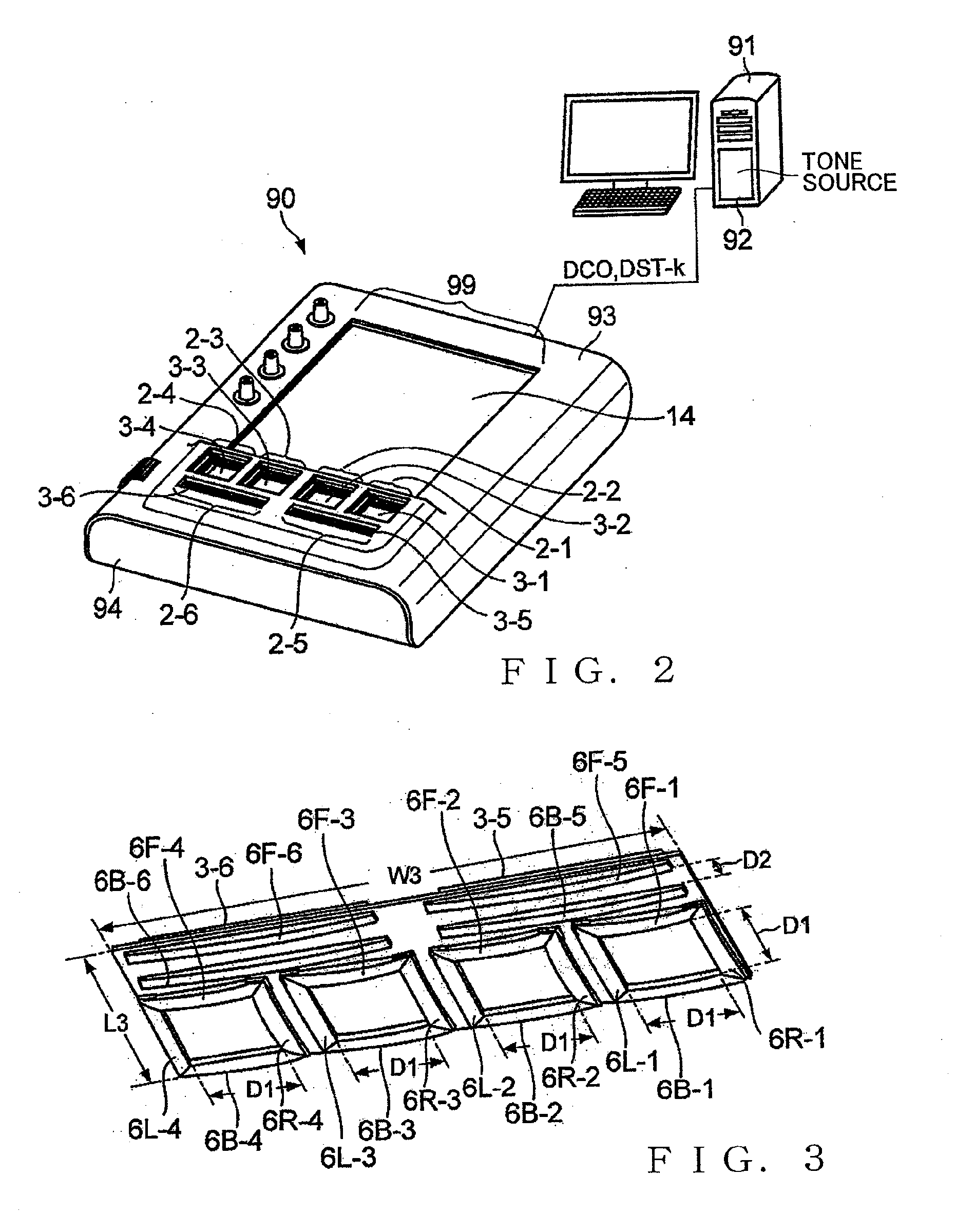
[0027]FIG. 1A is a perspective view showing a construction of an operation detection apparatus 10 according to a first embodiment of the present invention, and FIG. 1B is an exploded view of the operation detection apparatus 10. FIG. 2 is a view showing an operation terminal 90 having the operation detection apparatus 10 incorporated therein, and a personal computer 91 connected with the operation terminal 90. FIG. 2 is a view showing an operation terminal 90 having the operation detection apparatus 10 incorporated therein, and a personal computer 91 connected with the operation terminal 90. The operation detection apparatus 10 not only performs various displays in accordance with instructions given from the personal computer 91, but also detects operation for selecting from among various tone material data (data for use as materials for creating tones, in other words tone control data) and instruction reproduction of tone material data and supplies the personal computer 91 with sig...

second embodiment

[0055]FIG. 8 is a view showing example constructions of a second embodiment of the operation detection apparatus 10A and a tablet-type computer 97 to which the operation detection apparatus 10A is attached. The tablet-type computer 97 is of a rectangular parallelepiped shape having a horizontal dimension (width) W6 and longitudinal dimension (length) L6. A display surface 199 of an LCD (flat display device) having a horizontal dimension (width) W7 and longitudinal dimension (length) L7 slightly smaller than those of a surface 98 of the tablet-type computer 97 is exposed on the surface 98. The horizontal dimension W7 of the display surface 199 is substantially equal to the horizontal dimension W5 of the operation detection apparatus 10A, and the longitudinal dimension L7 of the display surface 199 is sufficiently greater than the longitudinal dimension L5 of the operation detection apparatus 10A. Further, a connector CNM (not shown in FIG. 8) having a plurality of types of pins, such...

third embodiment

[0065]FIG. 10 is a view showing example constructions of a third embodiment of the operation detection apparatus 10B and a tablet-type computer 97 to which the operation detection apparatus 10B is attached. The tablet-type computer 97 used with the third embodiment of the operation detection apparatus 10B is identical in construction to the tablet-type computer 97 used with the second embodiment of the operation detection apparatus 10A. The third embodiment of the operation detection apparatus 10B is different from the second embodiment of the operation detection apparatus 10A in that it does not include the band 120 provided in the second embodiment and includes four sucking disks 251, 252, 253 and 254 provide on four corner portions of the reverse surface of the transparent rigid member 18. The operation detection apparatus 10B is attached to a desired position on the display surface 199 by the sucking disks 251, 252, 253 and 254 being pressed against the display surface 199. The ...


PUM


Abstract

Operation detection apparatus includes a sensor section, and a pad formed of a transparent or translucent material and including at least one hitting portion provided on its surface. The hitting portion is suitable for being hit by a user. The sensor section is provided in a region positionally corresponding to the hitting portion under the pad, to detect hitting of the hitting portion. The sensor section includes a see-through portion provided in association with the hitting portion for allowing a region below the sensor section to be partly seen therethrough. The sensor section is sheet-shaped as a whole, and the see-through portion is an opening provided in a predetermined position of the sheet-shaped sensor section. Display area is located under the sensor section and exposed through the opening.

Description

BACKGROUND[0001]The present invention relates to techniques for detecting hitting, striking or beating (hereinafter referred to as “hitting”) performance operation.[0002]Among the conventionally-known electronic musical instruments are ones in which tone materials of different tone colors are allocated to a plurality of operating surfaces of a performance control and which, each time any one of the operating surfaces is hit, reproduce the tone material allocated to the hit operating surface. Examples of prior art literatures disclosing techniques related such electronic musical instruments include Japanese Patent Application Laid-open Publication No. 2010-113028 (hereinafter referred to as “relevant prior art literature”). The electronic musical instrument disclosed in the relevant prior art literature includes a total of twelve operating surfaces: six operating surfaces P1 to P6 located close to a human player or user; and six operating surfaces P7 to P12 located remote from the us...

Claims


Application Information

Patent Timeline
IPC IPC(8): G10H1/02
CPCG06F3/0238G10H3/146G10H2220/026G10H2220/096G10H2220/106H03K2217/96015G10H2220/561G10H2230/281G10H2240/311H03K17/9645G10H2220/241
Inventor TAKAHASHI, YUJI
Owner YAMAHA CORP
Features
  • R&D
  • Intellectual Property
  • Life Sciences
  • Materials
  • Tech Scout
  • Unparalleled Data Quality
  • Higher Quality Content
  • 60% Fewer Hallucinations
Learn More