
Fire stop system

Active Publication Date: 2012-01-19
PANDUIT
View PDF5 Cites 44 Cited by
  • Summary
  • Abstract
  • Description
  • Claims
  • Application Information

AI Technical Summary

Problems solved by technology

When a high temperature flame and combustion is present on one side of the wall, the shield or boot on the exposed side is typically destroyed.

Method used


Image

  • Fire stop system
  • Fire stop system
  • Fire stop system

Examples


Embodiment Construction

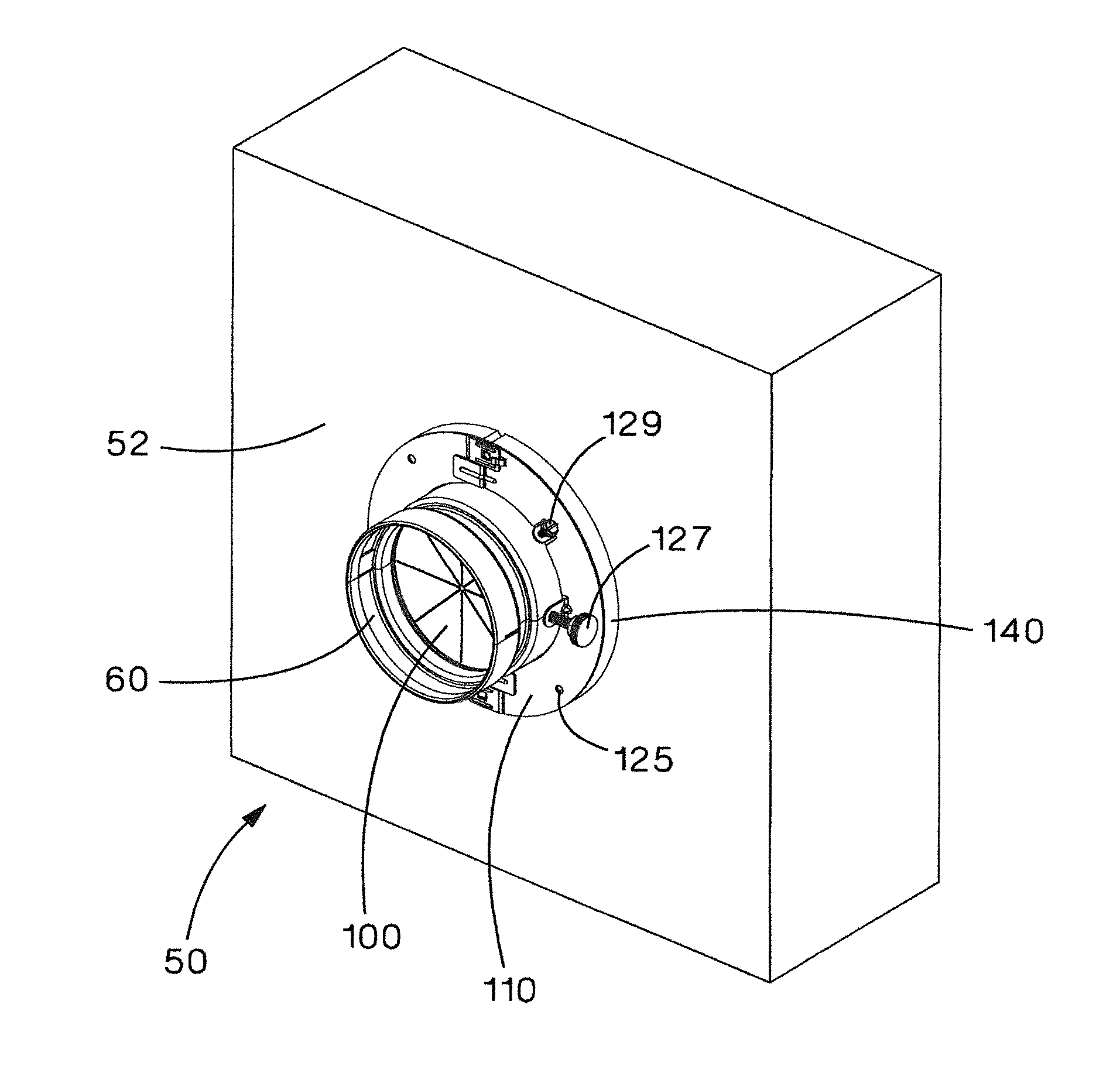
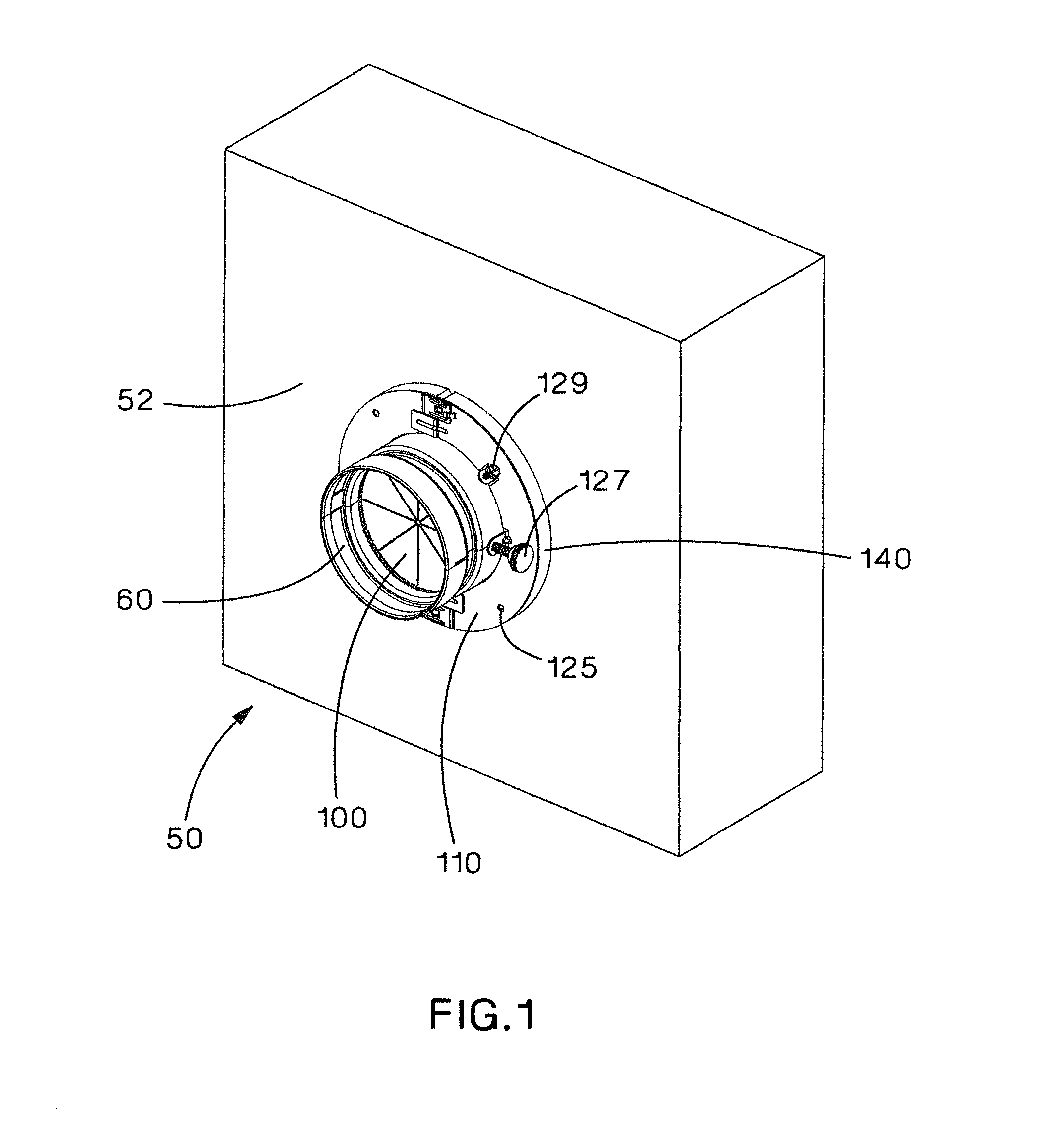
[0029]The present invention is directed to a fire stop system 50 with a pass through device horizontally installed in a wall or vertically installed in a floor. FIG. 1 illustrates the fire stop system 50 with the pass through device installed in a wall 52. The fire stop system 50 is designed to provide an F-rated and a T-rated system. The F-rating is the time in hours before a fire rated system allows the passage of flame through an opening in the system assembly. The T-rating is the time in hours that the non-fire side of a fire rated system does not exceed 325° F. above ambient temperature.

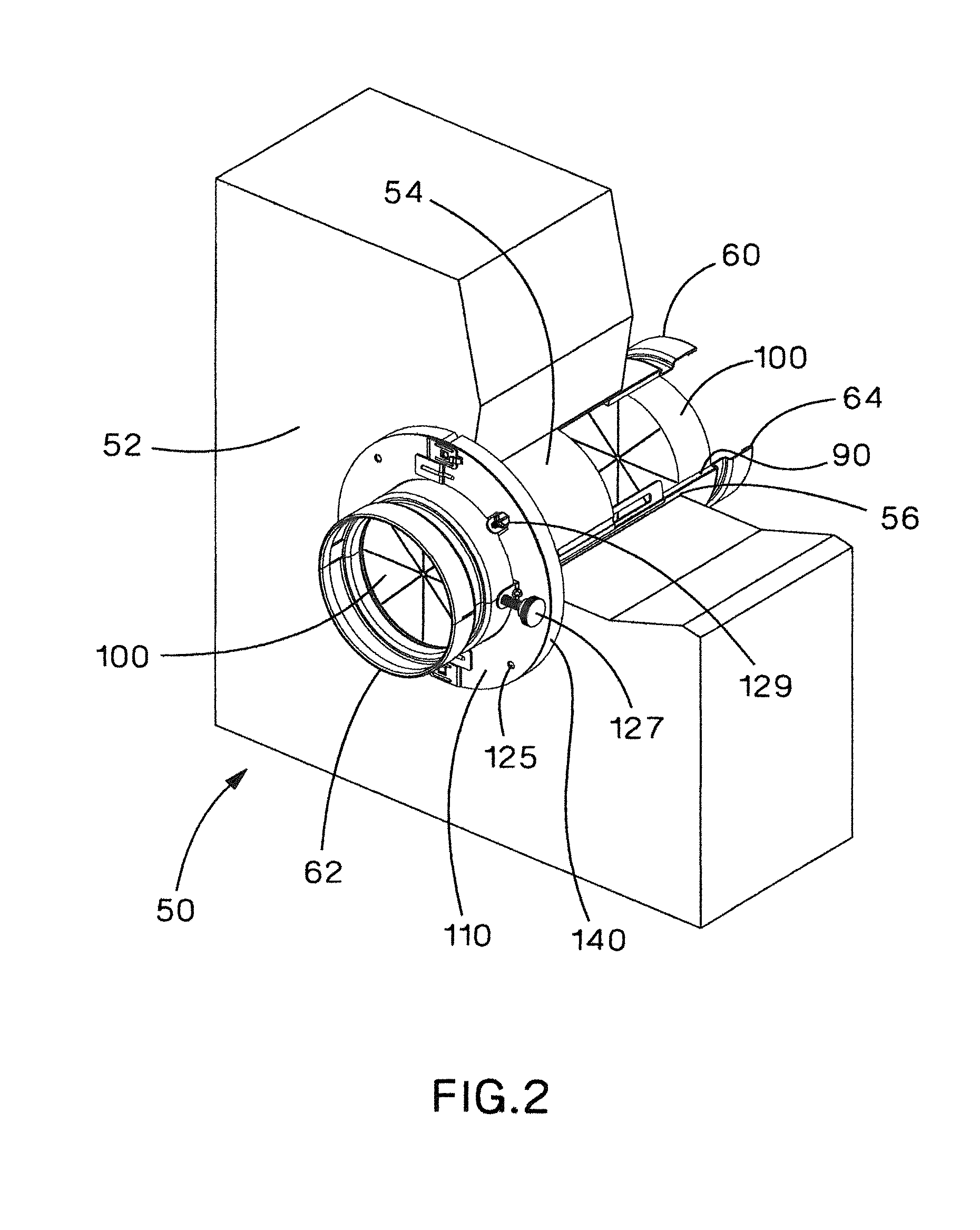
[0030]FIG. 2 illustrates a sectional view of the fire stop system 50 with the pass through device. As discussed below, the illustrated pass through device includes a split pipe 60 with a first end 62 and a second end 64. An intumescent material 90 and pie foam disks 100 are installed at both the first and second ends 62, 64 of the split pipe 60. As illustrated in FIG. 2, the pie foam disks 100 a...


PUM


Abstract

A fire stop system with a pass through device is installed in a structural opening. The fire stop system includes a split pipe, a foam wall gasket and an annulus plate. The split pipe includes a first end and a second end. The first end and the second end have an intumescent material installed thereon to seal the split pipe when the split pipe is exposed to elevated temperatures. The foam wall gasket is installed around the split pipe adjacent the structural opening. The foam wall gasket forms a contour to the structural opening blocking air flow between the split pipe and the opening. The annulus plate covers the foam wall gasket and is installed around the split pipe at the structural opening.

Description

CROSS-REFERENCE TO RELATED APPLICATION[0001]This application claims priority to U.S. Provisional Application No. 61 / 363,811, filed Jul. 13, 2010, the subject matter of which is hereby incorporated by reference in its entirety.FIELD OF THE INVENTION[0002]The present invention relates to a fire stopping pass through device, and more particularly to an improved fire stop system with a pass through device that includes an annulus plate and a split pipe.BACKGROUND OF THE INVENTION[0003]Fire stop systems designed to seal openings to prevent the spread of fires are well known. A fire stop system generally helps prevent the spread of smoke or flames throughout a facility, thereby limiting damage to the facility and providing building occupants more time to safely evacuate the facility.[0004]U.S. Pat. No. 4,086,736, for example, discloses a fire and liquid seal used in a structural wall. The fire seal includes a support pipe that extends through a wall. The support pipe is filled with a body...

Claims


Application Information

Patent Timeline
IPC IPC(8): A62C3/00
CPCA62C2/065H02G3/0412F16L5/04A62C3/16H02G3/22
Inventor ZERNACH, GARY L.DUKES, JOSEPH ALLENSAMPLES, TRAVIS M.YOUNGHOUSE, SCOTT M.PASCARELLA, NATHAN W.DUFFIELD, JOHN G.
Owner PANDUIT
Features
  • Generate Ideas
  • Intellectual Property
  • Life Sciences
  • Materials
  • Tech Scout
  • Unparalleled Data Quality
  • Higher Quality Content
  • 60% Fewer Hallucinations
Learn More