Dispenser
- Summary
- Abstract
- Description
- Claims
- Application Information
AI Technical Summary
Problems solved by technology
Method used
Image

Examples
first embodiment
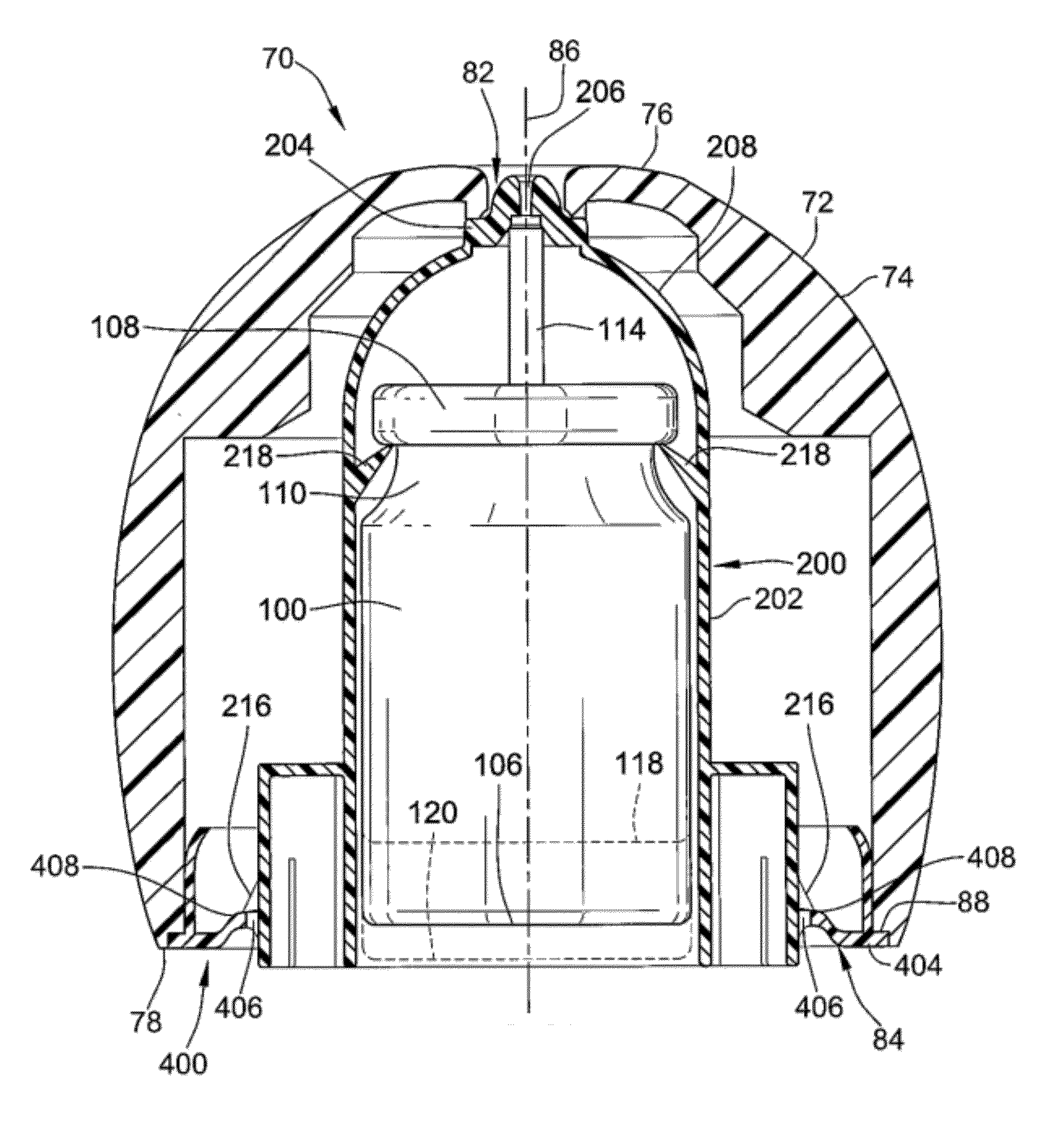
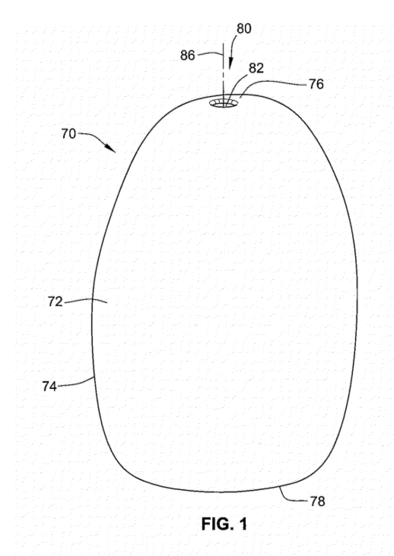
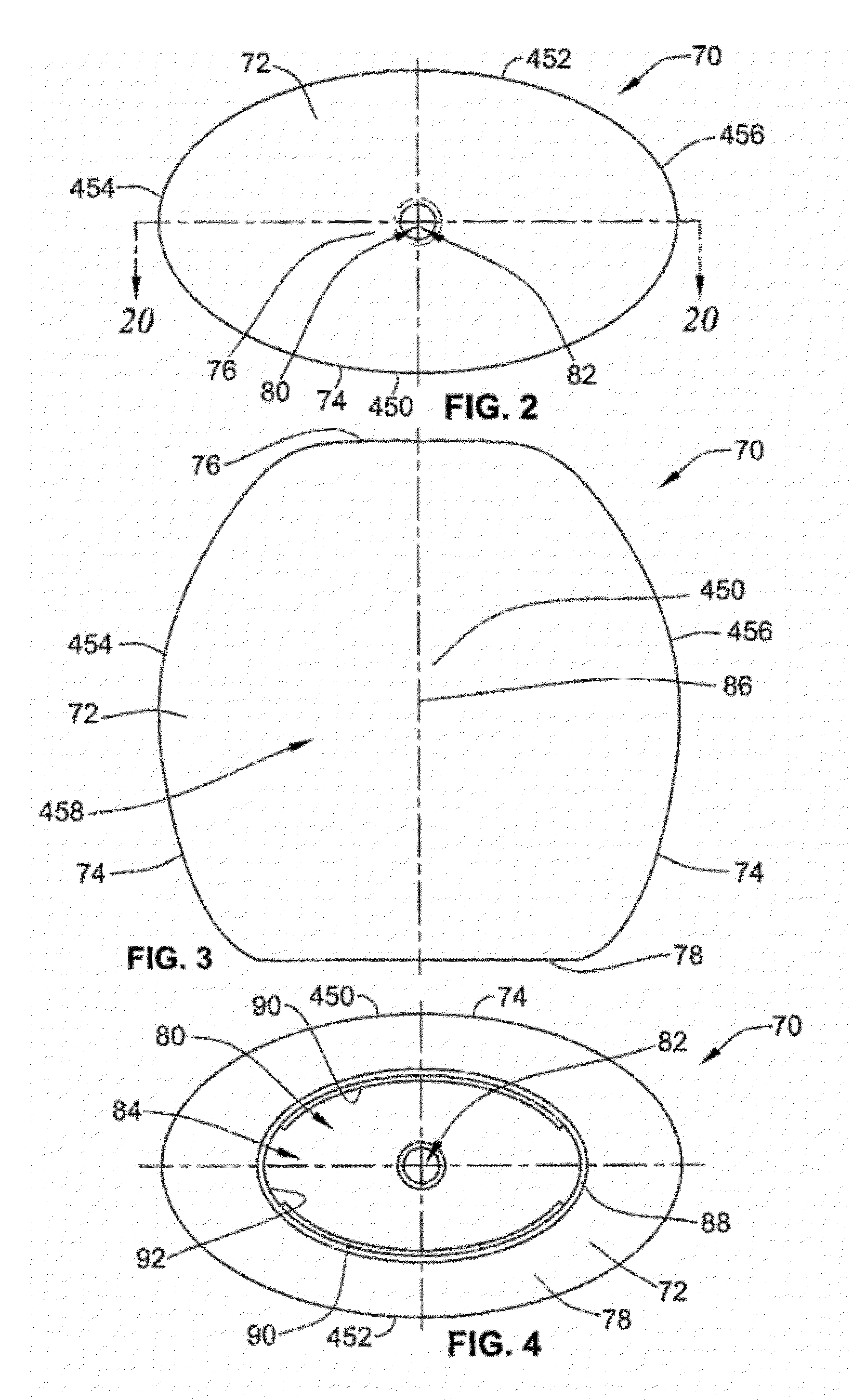
[0077]an aerosol dispenser 70 is depicted in FIGS. 1-4. The aerosol dispenser 70 includes a housing 72 having smooth or textured curvilinear sides 74 between a top end 76 and a bottom end 78. A bore 80 extends longitudinally through the housing 72 and includes a first aperture 82 at the top end 76 thereof and a second aperture 84 at the bottom end 78 thereof. The first and second apertures 82, 84 are each centered along a longitudinal axis 86 of the housing 72. As shown in FIG. 4, a groove 88 extends around a periphery of the second aperture 84. Two opposing lips 90 extend interiorly from a surface 92 of the housing 72 adjacent the groove 88.
[0078]A second embodiment of an aerosol dispenser 71 is shown in FIGS. 5-8. The aerosol dispenser 71 is similar to the first embodiment of the aerosol dispenser 70, except for the differences noted herein. A plurality of vertical elongate ribs 73 is disposed on an interior surface 75 of a housing 77. The housing 77 further includes two curviline...
second embodiment
[0084]Turning to FIGS. 15-19, an aerosol dispenser 230 (see FIG. 19) is shown. The aerosol dispenser 230 includes a shroud 250 (see FIG. 15). The shroud 250 is substantially similar to the shroud 200 discussed hereinabove with respect to FIGS. 10-13, except that the shroud 250 lacks the actuator socket 204 and the flexible members 208. In addition, the shroud 250 may have one or more support elements (not shown) running vertically, i.e., parallel to a longitudinal axis of the shroud 250, on the exterior surface 212 thereof, wherein each support element extends from one of the internal shoulders 218 toward the shoulders 210 or bottom end of the shroud 250. The support elements are sized to provide clearance within the bore 80 to allow for easy insertion therein and removal therefrom and to provide support to the internal shoulders 218 of the shroud 250, which abut the mounting cup 108 or collar of the container 100. Further, the support elements may be any shape, e.g., circular, tria...
third embodiment
[0087]FIGS. 21, 22, and 22A depict a shroud 322 adapted to be used with any of the aerosol dispensers as discussed previously herein. For purposes of the present discussion, the shroud 322 will be described in connection with the housing 77 depicted in FIGS. 5-8 and the container 100 shown in FIG. 9. The shroud 322 includes a cylindrical body portion 324 having a racetrack shaped skirt 326 that extends downwardly and outwardly therefrom. The skirt 326 is defined by a sidewall 328 having a bottom edge 330. A plurality of oval-shaped tabs 332 extend outwardly from the bottom edge 330. The tabs 332 are disposed adjacent corners of the skirt 326 and extend outwardly at an angle with respect to the bottom edge 330. The tabs 332 are adapted to catch on a bottom edge of an adapter 400 as discussed in more detail hereinbelow to prevent over insertion of the shroud 322 into the housing 72, 77. Although four tabs 332 are shown, any number of tabs having a variety of shapes may be used.
[0088]T...
PUM
 Abstract
Description
Claims
Application Information
 - R&D Engineer
- R&D Manager
- IP Professional
- Industry Leading Data Capabilities
- Powerful AI technology
- Patent DNA Extraction
Browse by: Latest US Patents, China's latest patents, Technical Efficacy Thesaurus, Application Domain, Technology Topic.
© 2024 PatSnap. All rights reserved.Legal|Privacy policy|Modern Slavery Act Transparency Statement|Sitemap