Method and System for Milling a Bevel Gear Tooth System in a Continuous Milling Process

a technology of bevel gear teeth and continuous milling, which is applied in the direction of gear teeth, gear manufacturing equipment, manufacturing tools, etc., can solve the problems of indexing process further, small deviation, and prolonging the total machining time duration

Active Publication Date: 2012-02-02
KLINGELNBERG AG
View PDF14 Cites 12 Cited by
  • Summary
  • Abstract
  • Description
  • Claims
  • Application Information

AI Technical Summary

Benefits of technology

[0019]It is an advantage of the invention that it is neither required to replace (change the clamping) the tool nor that a double head machine comprising two different tools need be employed.
[0020]The methods according to the invention can be performed both as a dry or a wet processing.
[0021]Other advantages and features of the invention become apparent from the other claims as well as from the following description of an exemplary embodiment of the invention, which shall be understood not to be limiting and which will be explained below with reference to the drawings.

Problems solved by technology

In the single indexing process described, the replacement of a cutter head takes place, which leads to a prolongation of the total machining time duration on one hand and that can involve inaccuracies on the other hand, as each clamping change or new clamping can lead to small deviations from the ideal position.
The indexing process further has the disadvantage that it involves so-called indexing errors.
With respect to other single-indexing processes, the completing process is characterized by a higher productivity (double chipping capacity); however a change of the flank shape is more difficult because changes in the kinematics of the machine will always have an influence on both flanks, just as with all processes comprising a two-flank-cut.
It is thus a disadvantage of the completing process that a change of a flank by means of the kinematics of the machine always involves a change of the other flank.

Method used


Image

  • Method and System for Milling a Bevel Gear Tooth System in a Continuous Milling Process
  • Method and System for Milling a Bevel Gear Tooth System in a Continuous Milling Process
  • Method and System for Milling a Bevel Gear Tooth System in a Continuous Milling Process

Examples


Embodiment Construction

[0031]In relation with the present description, terms are used which also find application in pertinent publications and patents. It is noted, however, that the use of these terms is to simply serve for a better comprehension. The inventive idea and the scope of the patent claims is not to be limited in their interpretation by the specific choice of the terms. The invention can be transferred without further ado to other terminology systems and / or technical fields. In other technical fields, the terms should be used analogously.

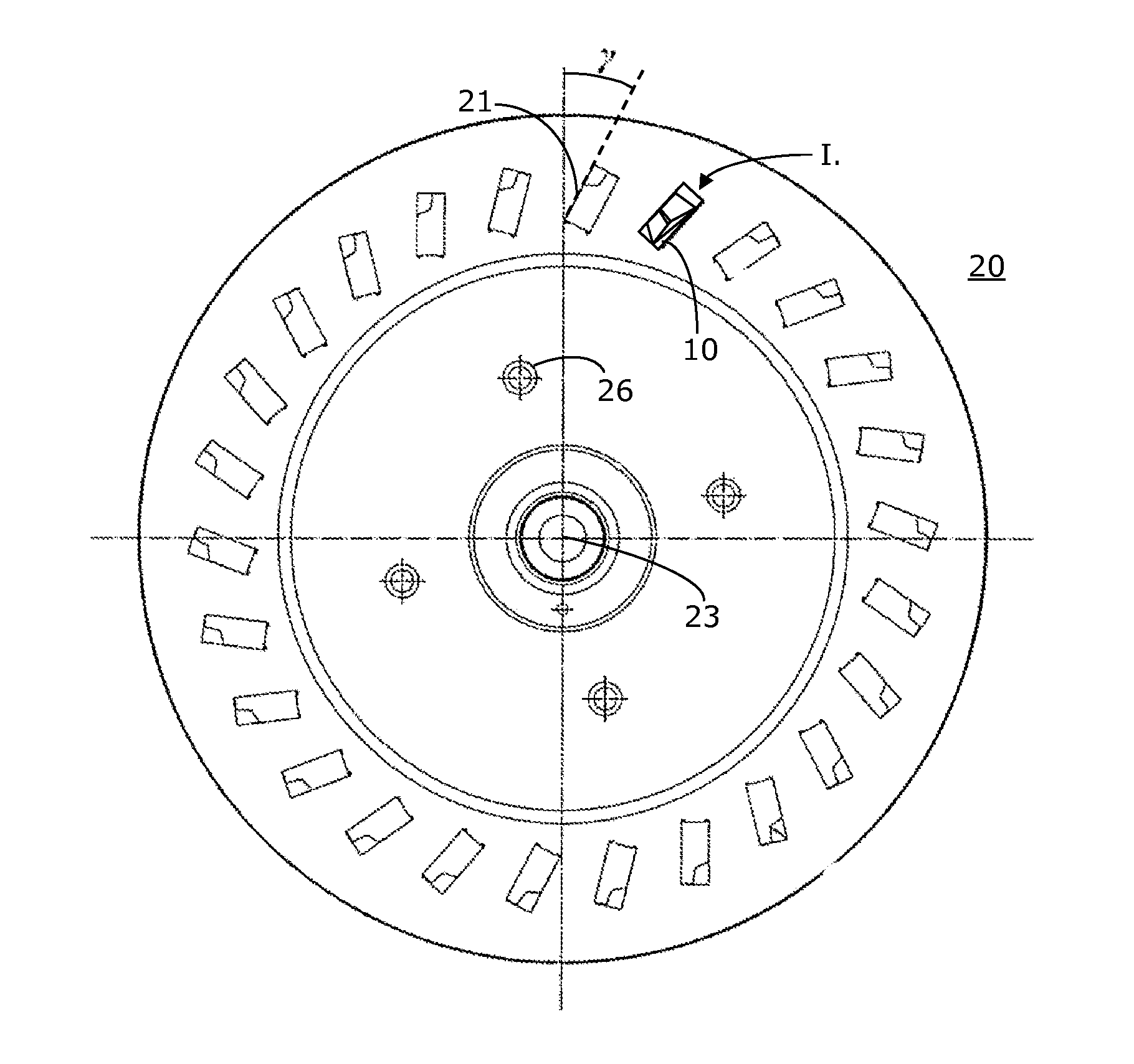
[0032]In the previously known continuous process, both tooth flanks are machined with the same tool radius (except corrections for generating the crowning etc.). The main cutting edges of the corresponding inner and outer cutters cross each other in the pitch plane. The inner cutter follows the outer cutter with an angular distance π / z0. Herein, z0 is the number of gears.

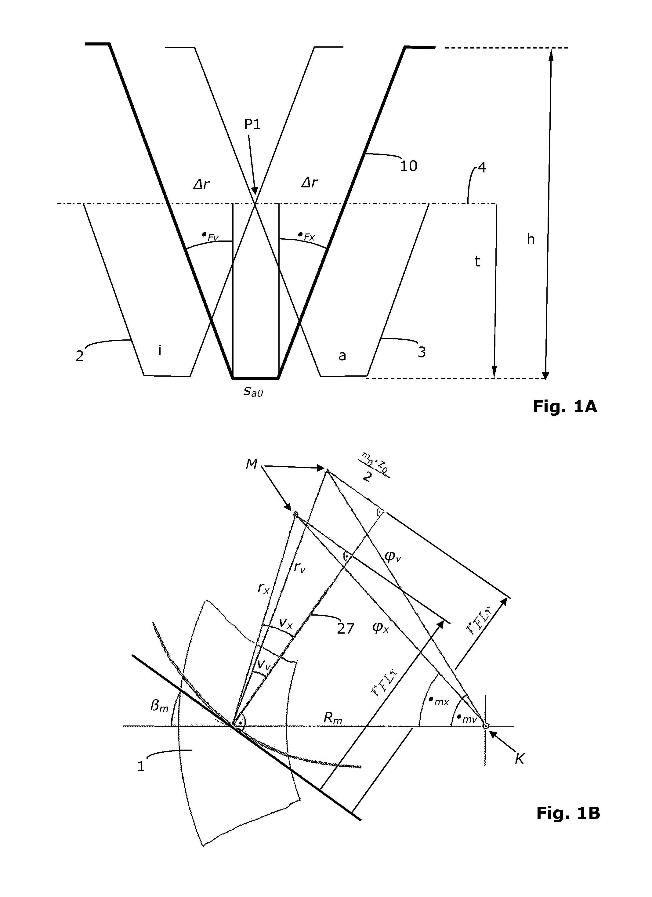
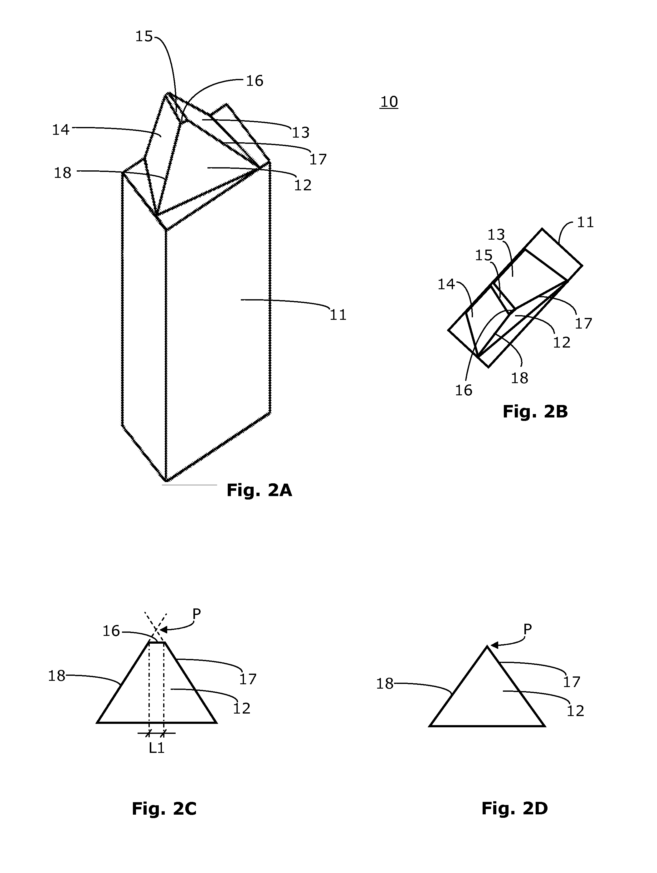
[0033]When the inner cutter 2 is joined with the outer cutter 3 to yield a single bar cut...


PUM

PropertyMeasurementUnit
fly circle radiusaaaaaaaaaa
distanceaaaaaaaaaa
pivot angleaaaaaaaaaa

Abstract

Milling of a bevel gear tooth system in the continuous process, wherein a cutter head comprising a plurality of pairs of inner cutting edges and outer cutting edges is applied to a workpiece, the inner cutting edges are arranged on a smaller fly circle radius than the outer cutting edges and movements for a metal-cutting machining by milling are performed by a gear cutting machine where the bevel work gear and the cutter head run linkedly: performing a first continuous metal-cutting machining by milling using the gear cutting machine according to a first machine setting, wherein convex inner flanks on the bevel work gear are machined by the inner cutting edges; and performing a second continuous metal-cutting machining by milling using a gear cutting machine according to a second machine setting, wherein concave outer flanks on the bevel work gear are machined by the outer cutting edges.

Description

CROSS-REFERENCE TO RELATED APPLICATIONS[0001]This application claims priority under 35 U.S.C. §119(a)-(d) to European Patent Application No. EP 10171235.4, filed Jul. 29, 2010, the contents of which are hereby incorporated by reference in their entirety as part of the present disclosure.FIELD OF THE INVENTION[0002]The present invention relates to milling a bevel gear tooth system in a continuous milling process, and in particular, to the milling of a spiral-shaped bevel gear tooth system.BACKGROUND OF THE INVENTION[0003]There are numerous methods for machining toothed wheels. In the chip-producing production of spiral bevel gears, a distinction is made between the single indexing process and the continuous process, which is also sometimes referred to as the continuous indexing process.[0004]In the continuous process (also referred to as face hobbing), for example, a cutter head tool comprises inner cutters and outer cutters, which are arranged group-wise, and is applied to a workpie...

Claims


Application Information

Patent Timeline
Patent Type & Authority Applications(United States)
IPC IPC(8): B23F9/14
CPCB23F9/105B23F21/226Y10T409/106042Y10T409/103975B23F23/006B23F1/06B23F5/20B23F5/24B23F23/00
Inventor KREH, WILHELM
Owner KLINGELNBERG AG
Why Eureka
Try Eureka