Fish landing net

a fishing net and net frame technology, applied in fishing nets, fishing applications, fishing, etc., can solve the problems of limiting the load that could be received in the net, requiring many parts, and the handling would sometimes bind or at least not slide easily,

Active Publication Date: 2012-02-16
STEFFENS DAVID A
View PDF59 Cites 29 Cited by
  • Summary
  • Abstract
  • Description
  • Claims
  • Application Information

AI Technical Summary

Problems solved by technology

As an example, as a result of using an aluminum handle and an aluminum connecting member, the handle would sometimes bind or at least would not slide easily

Method used


Image

  • Fish landing net
  • Fish landing net
  • Fish landing net

Examples


Embodiment Construction

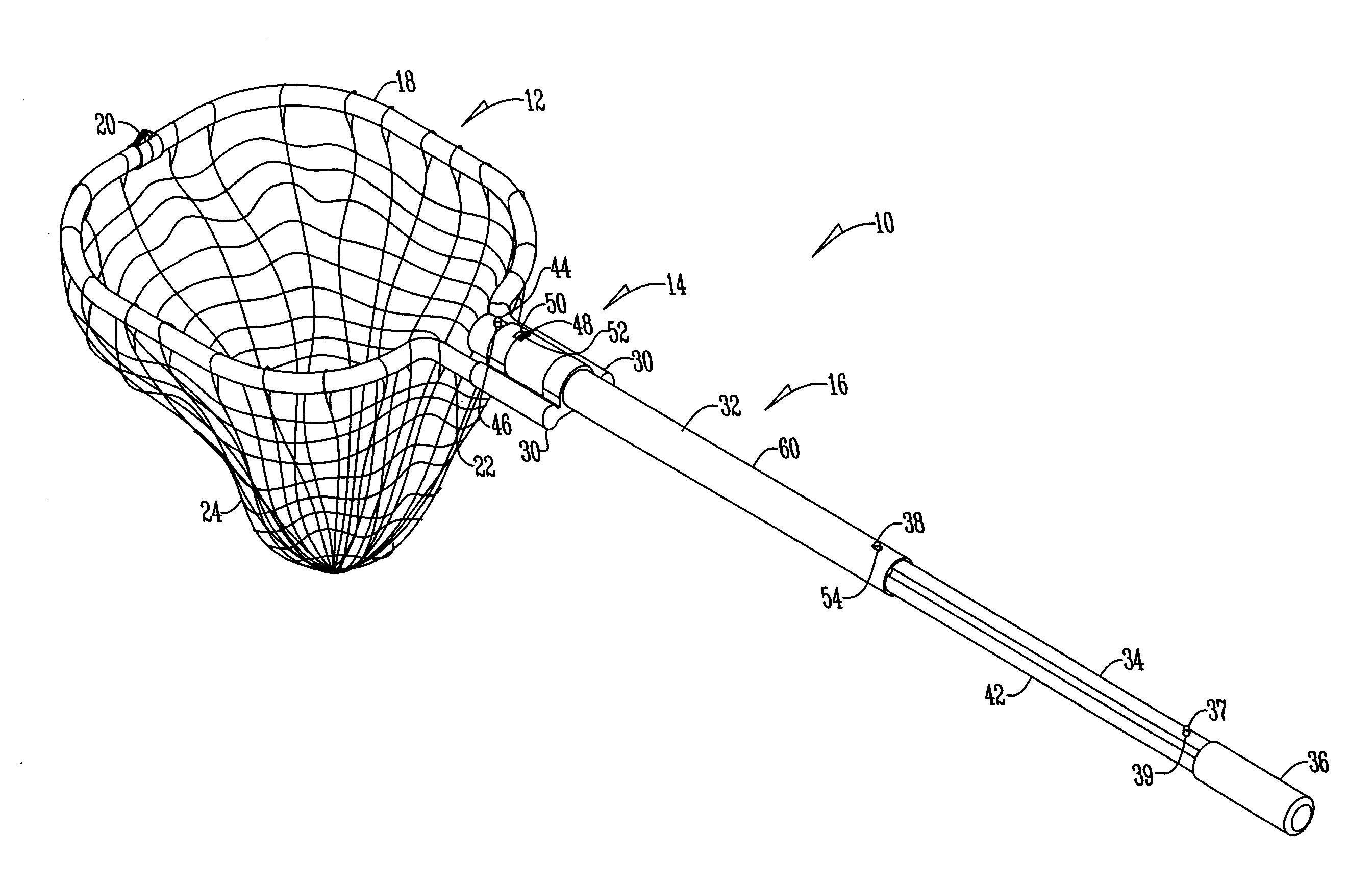
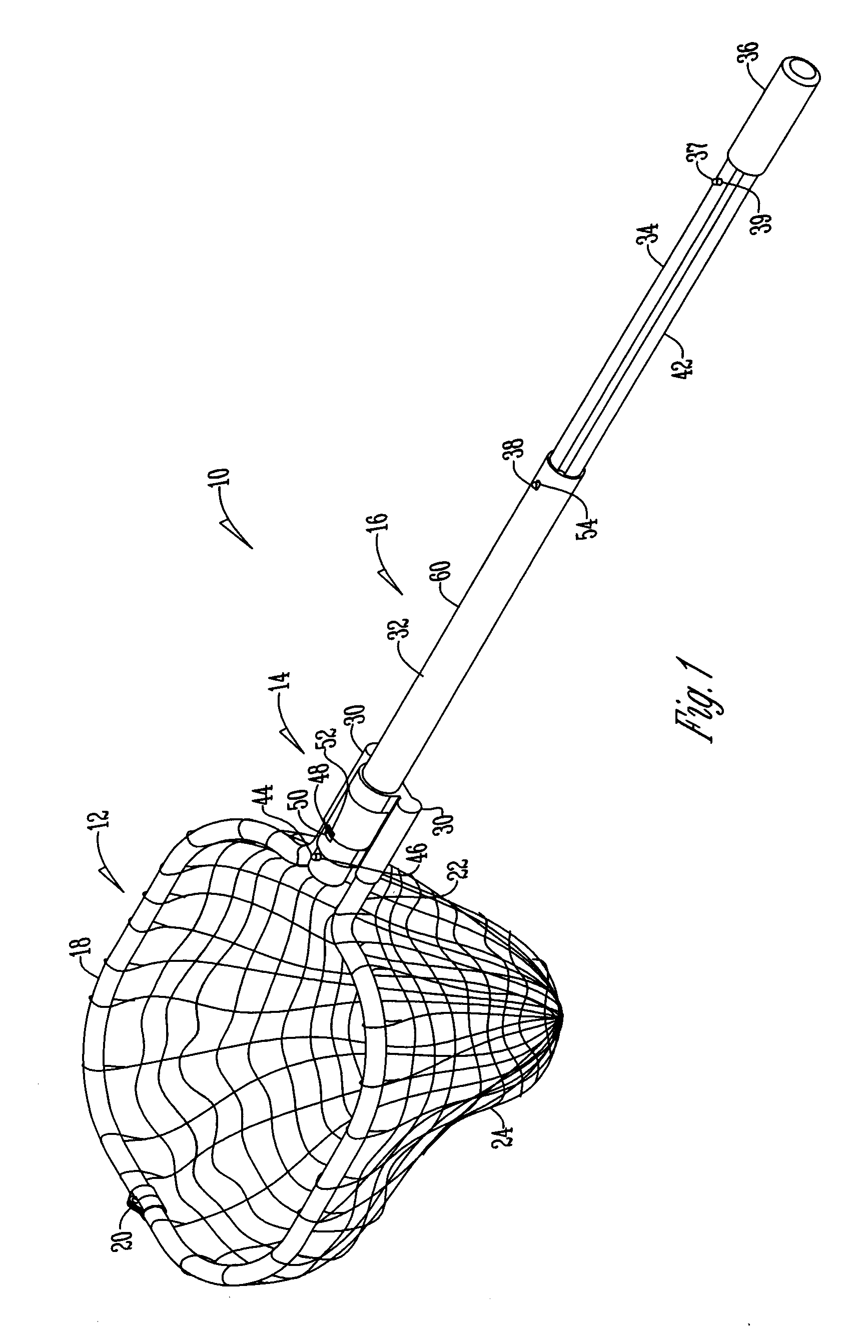
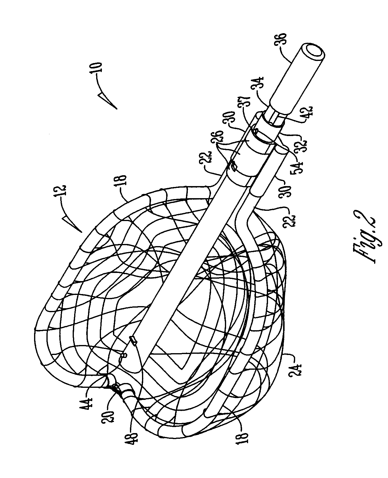
[0012]Referring to the Figures, the landing net 10 has a net member 12, a connecting member 14, and a handle 16. The net member 12 has a pair of frame members 18 that are foldably or pivotally connected at a first end 20 and are attached at a second end 22 to the connecting member 14. The frame members 18 are threaded through mesh netting 24.

[0013]The connecting member 14 has at least two and preferably three locking rings 26 that are in alignment with one another. Each ring 26 has a groove 28 formed on the inner surface of the ring 26 with the grooves 28 of each ring 26 also being in alignment. Attached to the inner surface of each ring is a plastic bushing 29. The bushing provides a barrier between the handle 16 and the connecting member 14 to allow the two pieces to slide more easily. Attached to the rings 26 are a pair of hollow receivers 30 that are formed to receive the second end 22 of the frame members. The receivers 30 are generally parallel to the longitudinal axis of the ...


PUM


Abstract

A landing net having a net member attached to a connecting member that is attached to a handle. The connecting member has at least two locking rings and a receiver attached to each locking ring. Each locking ring has a bushing attached to an inner surface of the ring. The receivers have a non-circular shape and extend parallel to a central axis of the rings.

Description

BACKGROUND OF THE INVENTION[0001]This invention is directed toward fishing, and more particularly to an improved fishing net.[0002]Fishing nets are well known in the art. As an example, U.S. Pat. No. 5,533,293 by Boehm, incorporated by reference herein in its entirety, discloses a foldable landing net with a telescoping handle that used fewer parts that were all connected together for both transport and use. While Boehm '293 represented an improvement in the art, deficiencies remained. As an example, as a result of using an aluminum handle and an aluminum connecting member, the handle would sometimes bind or at least would not slide easily. Also, the manner of joining the net frame to the connecting member required many parts, was costly, and limited the load that could be received in the net. Therefore, a need exists in the art for a fish landing net that addresses these deficiencies.[0003]An objective of the present invention is to provide a fishing net where the handle slides eas...

Claims


Application Information

Patent Timeline
IPC IPC(8): A01K77/00A01K75/00
CPCA01K77/00
Inventor STEFFENS, DAVID A.
Owner STEFFENS DAVID A
Why Eureka
Try Eureka