Yoga mat with support and traction

a technology of yoga mats and supports, applied in the field of yoga mats and yoga towels, can solve the problems of increasing the likelihood of injury, reducing the performance of users, and inability to provide sufficient traction in certain areas of yoga mats

Active Publication Date: 2012-03-29
SEQUENCE
View PDF4 Cites 35 Cited by
  • Summary
  • Abstract
  • Description
  • Claims
  • Application Information

AI Technical Summary

Benefits of technology

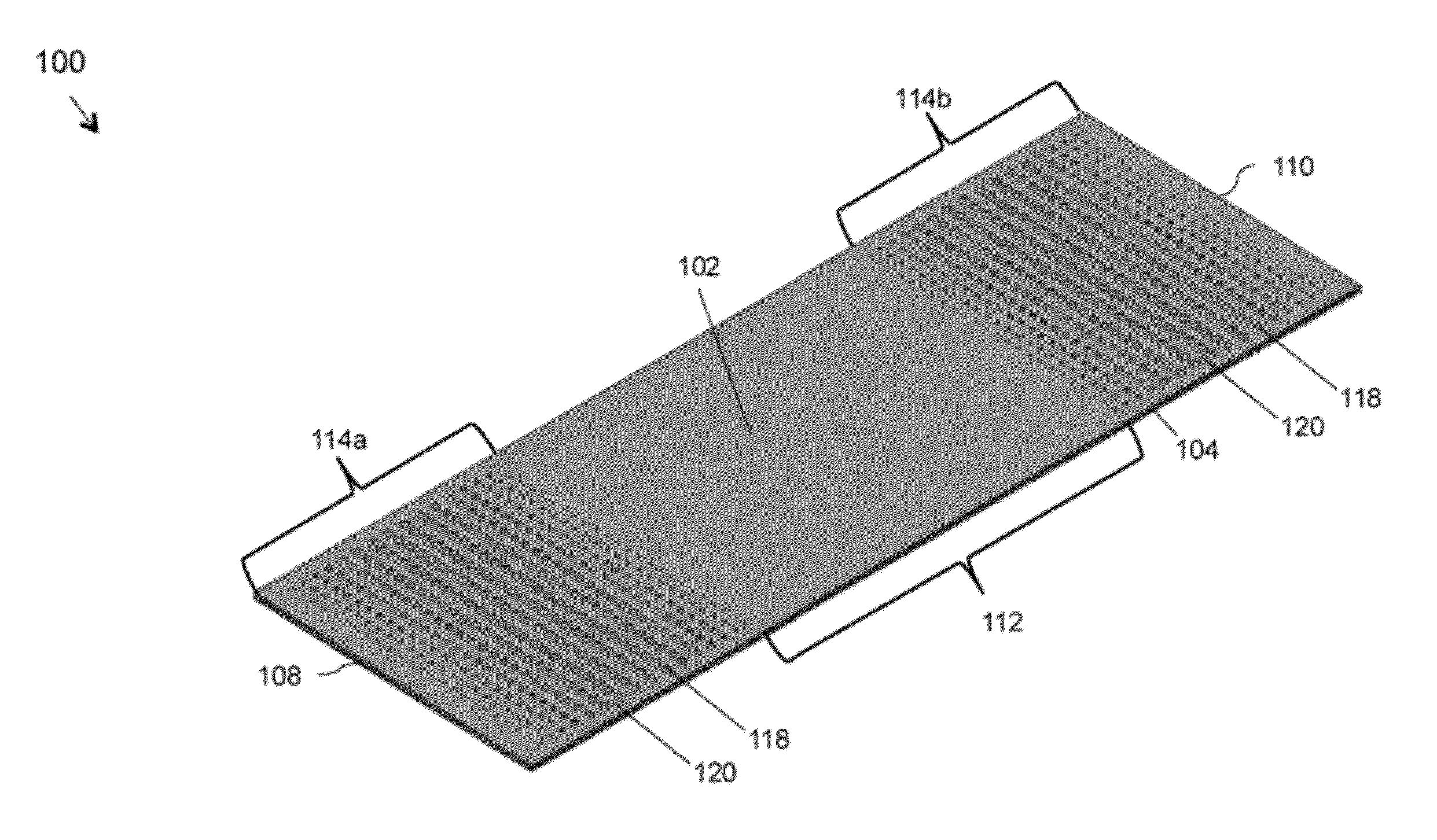
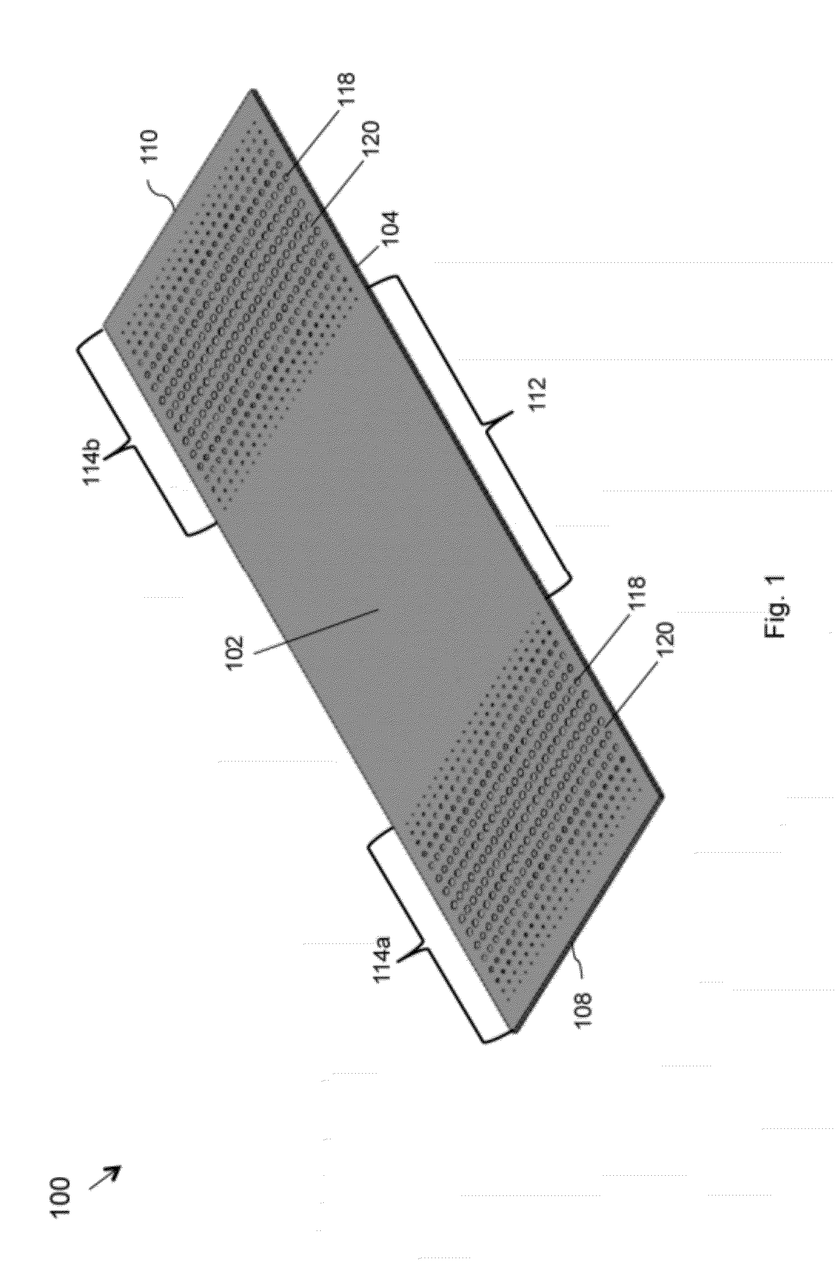
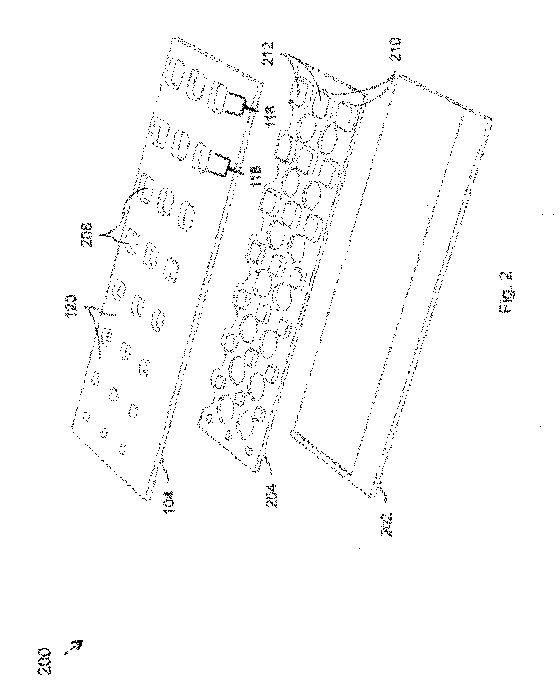
[0012]The present invention may provide a mat including a first layer that may be formed of a compressible first material. The first layer may comprise an upper surface with one or more first portions and one or more second portions. The mat may further include at least one opening formed through the first portions. Further, the mat may include at least one column that may be disposed in or proximate to the openings. The columns may be formed of a second material. Further, the second portions may be adapted to be depressed in a compressed configuration. Further, the columns may be adapted to provide either support to a body part in a direction perpendicular to the top surface of the first layer, or traction to a body part in a direction tangential to the first layer's top surface, or both, when the second portions are depressed.
[0013]The present invention may further provide a mat including a first layer that may be formed of a compressible first material. The first layer may include an upper surface with one or more first portions and one or more second portions. The mat may further include one or more openings formed through the first portions. Further, the mat may include one or more columns that may be disposed in or proximate to the openings. The columns may be formed of a second material. Further, the columns may be configured to be depressed in a compressed configuration. Further, the second portions may be adapted to provide fraction to a body part in a direction tangential to the first layer's top surface when the columns are depressed.
[0014]The present invention may further provide a towel that may include an absorption layer that may be adapted to absorb moisture. The absorption layer may include a top surface with one or more first portions and one or more second portions. The towel may further include at least one compressible region of flexible fiber that is disposed on the first portions. The compressible regions of flexible fiber may be formed of a flexible first material. The towel may further include one or more columns that may be disposed on the second portions. The columns may be formed of a second material. Further, the columns may be adapted to provide either support to a body part in a direction perpendicular to the absorption layer's top surface, or fraction to a body part in a direction tangential to the absorption layer's top surface, or both, when the compressible regions of flexible fiber are depressed.
[0015]The present invention may further provide a towel that may include an absorption layer adapted to absorb moisture. The absorption layer may include a top surface with one or more first portions and one or more second portions. The absorption layer may further include at least one compressible region of flexible fiber that is disposed on the first portions. The compressible regions of flexible fiber may be formed of a flexible first material. The towel may further include at least one column that may be disposed either in or proximate to at least one opening formed through the second portions. The columns may be formed of a second material. Further, the columns may be adapted to provide either support to a body part in a direction perpendicular to the absorption layer's top surface, or traction to a body part in a direction tangential to the absorption layer's top surface, or both, when the compressible regions of flexible fiber are depressed.
[0016]In an aspect of the invention, a grip apparatus is provided. The grip apparatus may include a first layer formed of a compressible first material. The grip apparatus may further include an upper surface with one or more first portions and one or more second portions. The grip apparatus may further include at least one opening formed through the first portions. Further, the grip apparatus may include at least one column that may be disposed in or proximate to the openings. The columns may be formed of a second material. Further, either the second portions may be adapted to provide traction in a direction tangential to the first layer's upper surface when the columns, which are adapted to be compressed to a depressed configuration, are depressed, or the columns may be adapted to provide either support in a direction perpendicular to the upper surface of the first layer, or traction in a direction tangential to the first layer's upper surface, or both, when the second portion, which is adapted to be compressed to a depressed configuration, is depressed.
[0017]The present invention may further provide a grip apparatus that may include an absorption layer adapted to absorb moisture. The absorption layer may include a top surface with one or more first portions and one or more second portions. The absorption layer may further include at least one compressible region of flexible fiber that is disposed on the first portions. The compressible regions of flexible fiber may be formed of a flexible first material. The towel may further include at least one column that may be formed of a second material. The columns may also be disposed either on the second portions or in / proximate to openings formed through the second portions. The columns may be further adapted to provide either support in a direction perpendicular to the absorption layer's top surface, or traction to in a direction tangential to the absorption layer's top surface, or both, when the compressible region of flexible fiber is depressed.

Problems solved by technology

A limitation of such mats is that they are unable to provide sufficient traction in certain areas of the mats.
The sweating on the mat may significantly reduce the performance of the user and may also increase the likelihood of injuries due to slipping.
Additionally, the single material construction of the mats does not fully address the varying requirements of the user during various yoga postures on different locations of the mats.
None of the existing designs for the mats and towels provides secure grip and stability during yoga poses, and smooth and unobstructed movements between yoga poses in a single product.
In addition, no existing design uses the difference in the compressibility of the grip regions and the rest of the mat or towel body.
Similarly, none of the existing designs for a grip apparatus provide secure grip and stability when pressure is applied, and smooth and unobstructed movement when pressure is released.

Method used


Image

  • Yoga mat with support and traction
  • Yoga mat with support and traction
  • Yoga mat with support and traction

Examples


first embodiment

[0069]FIGS. 4A and 4B depict compressed and uncompressed configurations of a mat 400, in accordance with the present invention. As shown in FIGS. 4A and 4B, the mat 400 includes a first layer 402 having a top surface 408 and a bottom layer 404 disposed below the first layer 402. The top surface 408 of the first layer 402 in the grip zone may include one or more first portions 410. The top surface 408 of the first layer 402 in the grip zone other than the first portions 410 forms one or more second portions 412. As shown in FIGS. 4A and 4B, the second portions 420 are the portions on the top surface 408 of the first layer 402 in the grip zone that are disposed between the first portions 410.

[0070]As depicted in FIGS. 4A and 4B, a plurality of columns 414 formed of an elastomer may be introduced into openings 418 formed through the first portions 410. The columns 414 may have the top surfaces 420 that are coplanar to the top surface 408 of the first layer 402. Further, as shown in FIG...

second embodiment

[0074]FIGS. 5A and 5B depict compressed and uncompressed configurations of a mat 500, in accordance with the present invention. Various elements or configurations in this embodiment are the same as that disclosed in conjunction with FIGS. 4A and 4B, except that columns 502 are constructed differently. The individual columns 502 are formed by pouring the liquid elastomer into the openings 418 and curing the elastomer. As a result, the sides of the columns 502 are bonded to the sides of the openings 418. Further, as illustrated in FIG. 5B, the sides of the openings 418 are only partially compressed and thus, only a small portion of the columns 502 is exposed to the top surface 408 of the first layer 402 when subjected to pressure equal to or greater than the threshold pressure. However, portions of the individual second portions 412 of the top surface 408 of the first layer 402 surrounding the columns 502 compress such that the columns 502 protrude further than the surrounding portion...

third embodiment

[0075]FIGS. 6A and 6B depict compressed and uncompressed configurations of a mat 600, in accordance with the present invention. Various elements or configurations in this embodiment are the same as that disclosed in conjunction with FIGS. 4A and 4B, except that columns 602 are formed of a material that is more compressible than the material used to form the second portions 412 of the top surface 408 of the first layer 402. As a result, as illustrated in FIG. 6B, top surfaces of the columns 502 depress or compress more than the second portions 412 in response to the pressure applied on the grip zone. In one embodiment, the threshold pressure at which the columns 502 may begin to compress may be different from the threshold pressure at which the second portions 412 may begin to compress. Alternatively, in another embodiment, the threshold pressures for both the columns 502 and the second portions 412 may be the same; however, the columns 502 may compress more than the second portions ...


PUM

PropertyMeasurementUnit
compressibleaaaaaaaaaa
thicknessaaaaaaaaaa
thicknessaaaaaaaaaa

Abstract

The present disclosure provides a mat including a compressible first layer, openings formed through one or more first portions and columns disposed in/proximate to the openings. One or more second portions, or at least one column, or both may be configured to be depressed to provide support and traction. The present disclosure further provides a towel including an absorption layer and a compressible region of flexible fiber disposed on one or more first portions of a top surface of the absorption layer. The towel may further include one or more columns disposed either on one or more second portions or in/proximate to openings formed through the one or more second portions. The compressible region of flexible fiber may be configured to be depressed in a compressed configuration to provide support and traction. The mat or the towel may be further adapted to form a grip apparatus.

Description

CROSS-REFERENCE TO RELATED APPLICATIONS[0001]This application claims the benefit of the following provisional applications, each of which is hereby incorporated by reference in its entirety:[0002]U.S. Provisional Application 61 / 369,656, filed Jul. 30, 2010; and U.S. Provisional Application 61 / 410,422, filed Nov. 5, 2010.BACKGROUND[0003]1. Field[0004]The present invention generally relates to yoga accessories and more specifically to yoga mats and yoga towels.[0005]2. Description of the Related Art[0006]Yoga has become one of the popular ways and techniques of maintaining physical as well as mental health and fitness. The art of yoga has gained momentum, especially in the past decade, across the world with millions of people adopting it. This has led to a surge in the demand for yoga accessories such as yoga mats, yoga towels, and the like that may utilize modern manufacturing and design processes to create products with desired comfort levels, thereby meeting the requirements of a y...

Claims


Application Information

Patent Timeline
Patent Type & Authority Applications(United States)
IPC IPC(8): B32B3/24A47G9/06
CPCA63B6/00A63B21/1473Y10T428/24479Y10T428/24339Y10T428/24331A63B2209/026A63B21/4037
Inventor FRANKS, LISA M.CONNAUGHTON, STEPHANIE F.TINSTMAN, MICHAEL D.GERNETZKE, THOMAS A.DAYTON, DOUGLAS C.DUNCANSON, DAVID E.KHALIFA, ALY G.LAZARCHIK, DANIEL B.
Owner SEQUENCE
Why Eureka
Try Eureka