Warning stanchion

a technology of stanchion and stanchion, which is applied in the direction of burglar alarms, portable traffic signalling, instruments, etc., can solve the problems of damage and failure of existing warning systems such as cones

Inactive Publication Date: 2012-05-17
TEUCHERT JOSEPH JOHN
View PDF4 Cites 25 Cited by
  • Summary
  • Abstract
  • Description
  • Claims
  • Application Information

AI Technical Summary

Problems solved by technology

While such measures are sometimes effective, sometimes they are not, resulting in a collision with a plane.
And when the current systems fail and a vehicle runs into a parked aircraft, dam...

Method used


Image

  • Warning stanchion
  • Warning stanchion
  • Warning stanchion

Examples


Embodiment Construction

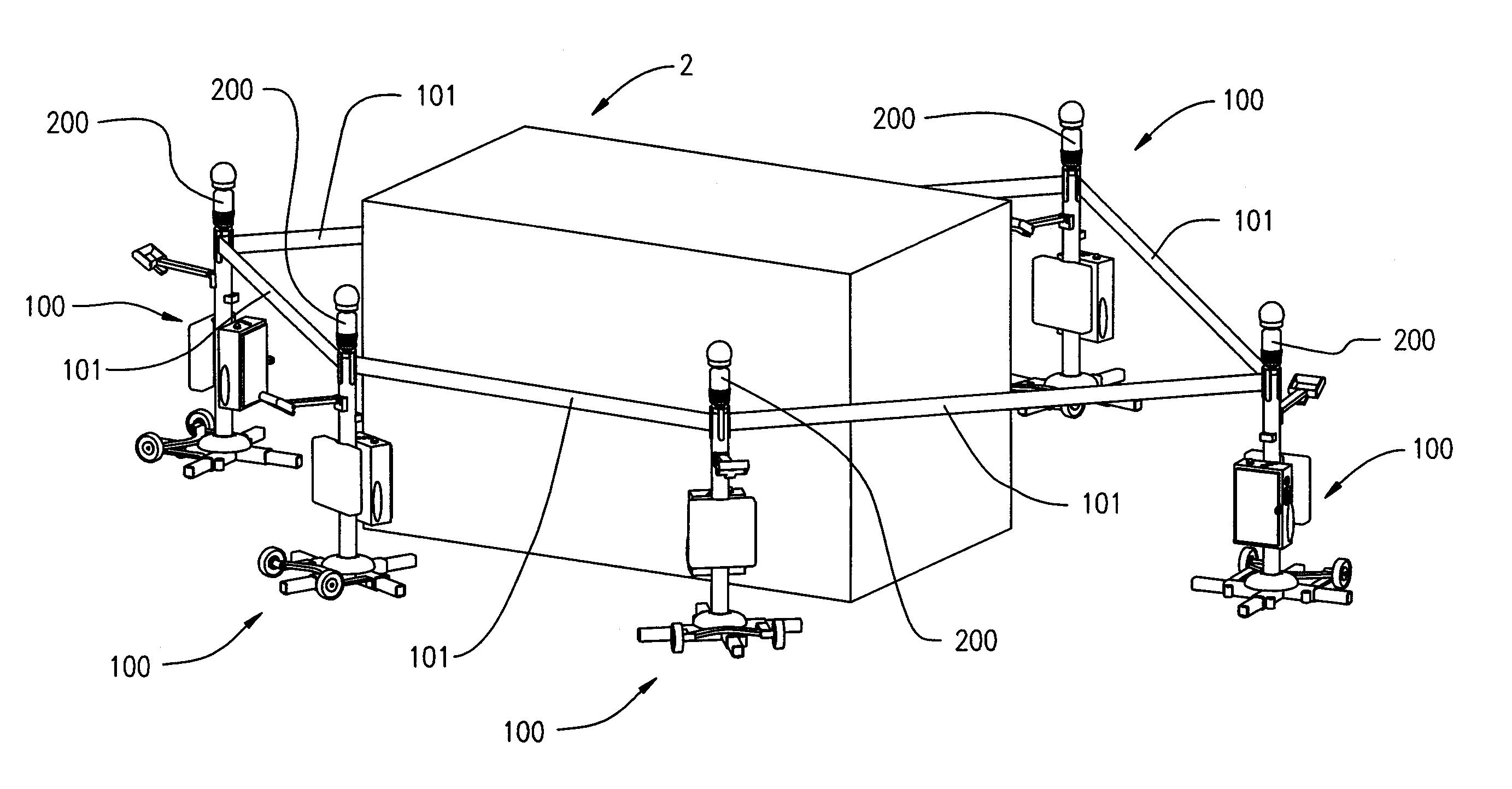
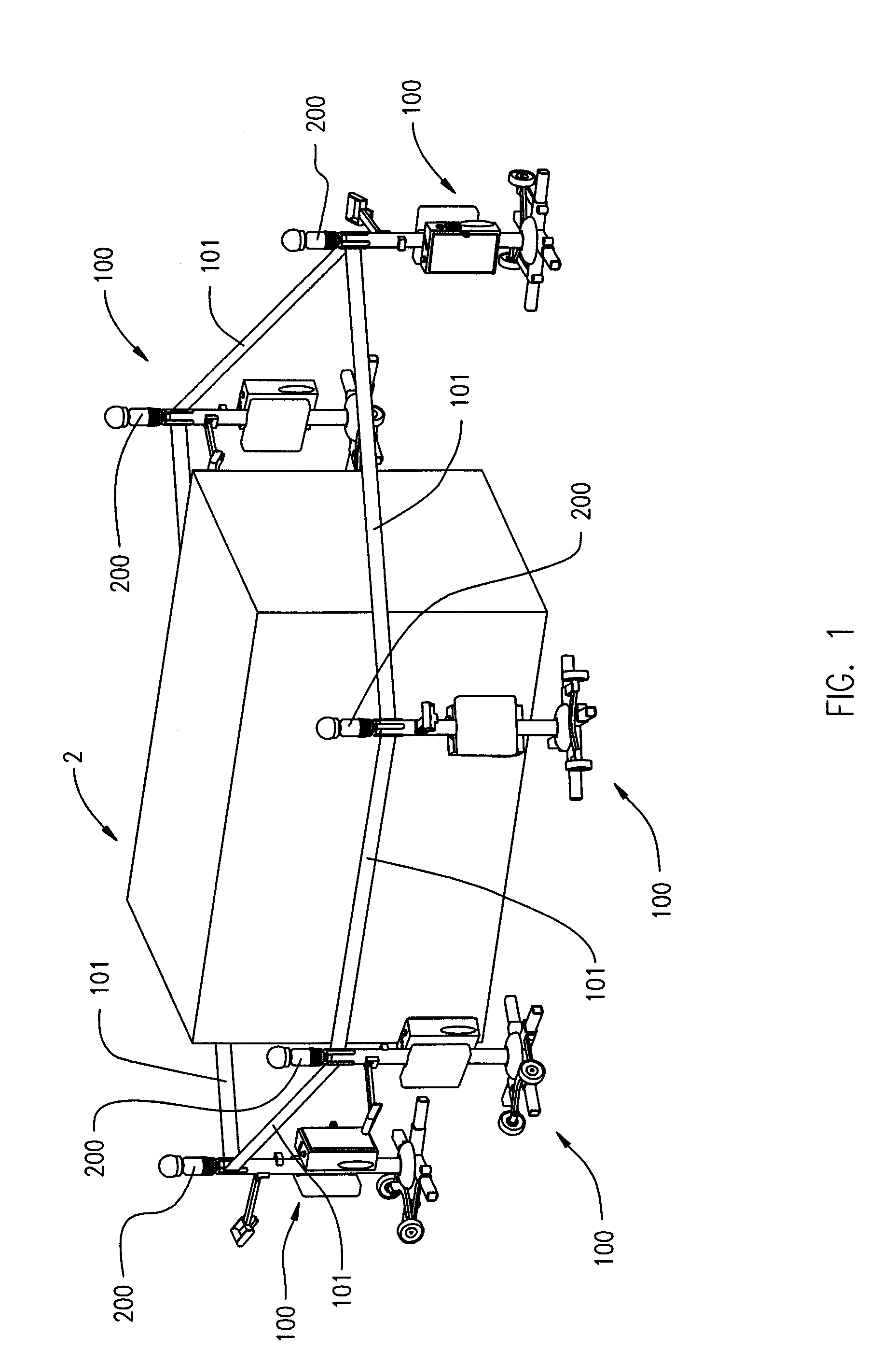
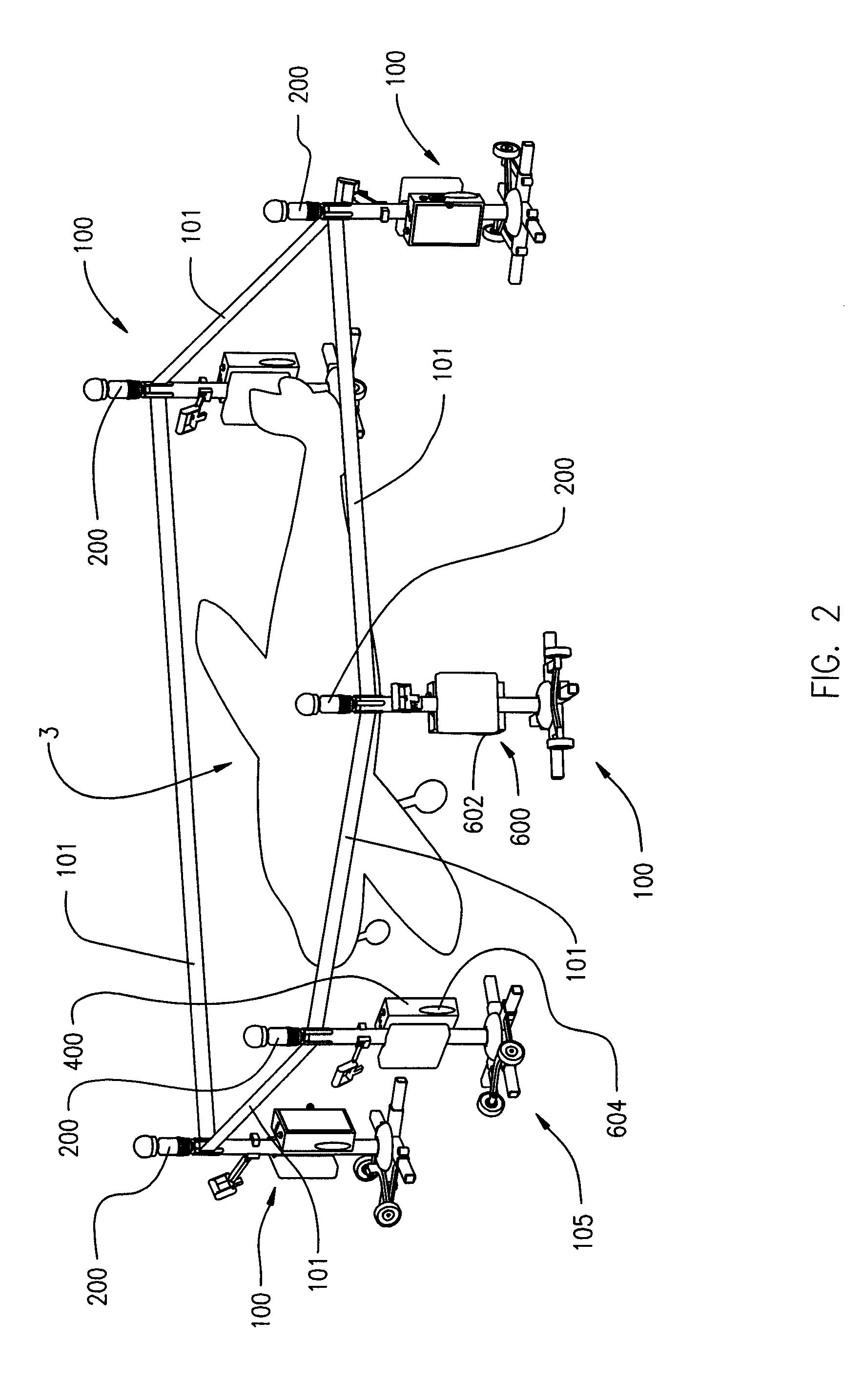
[0019]FIG. 1 shows a warning system having plurality of warning stanchions 100, each warning stanchion 100 stationed about at least a portion of the perimeter of an area surrounding an object 2 to warn a person that an approaching vehicles or other moving object of a breach of the perimeter and a potential collision with the object. Barrier elements 101 communicate between adjacent warning stanchions 100. If the moving vehicle or other moving object breaches one of the barriers 101, then at least one warning signal generating device 200 is activated. FIG. 2 shows the warning system having a plurality of warning stanchions 100 stationed about at least a portion of the perimeter of and area surrounding an airplane 3 (not to scale).

[0020]As shown in FIG. 3, the warning stanchion 100 includes a vertical support structure 102 having an upper section 104, a middle section 107, and a lower section 106. The upper section 104 includes a warning signal generator 200 and a barrier receptacle 3...


PUM


Abstract

A warning stanchion that has a vertical support structure, a belt receptacle affixed to the vertical support structure, a tilt sensor, and a warning signal generator in communication with the belt receptacle and the tilt sensor. Typically, a plurality of the warning stanchions are used to created a warning barrier around an object so that the warning signal generates a signal when the warning barrier is breached. The warning signal generator may emit a visual warning, an audio warning, or a frequency signal.

Description

CROSS-REFERENCE TO RELATED APPLICATION[0001]This application claims the benefit of U.S. Provisional Patent Application No. 61 / 412,616 filed on Nov. 11, 2010, the disclosure of which is incorporated herein by reference in its entirety.FIELD OF INVENTION[0002]This invention relates generally to a warning stanchion and specifically to warning stanchions used for creating a barrier warning system to prevent vehicles from colliding with objects.BACKGROUND OF THE INVENTION[0003]Airport ramps or aprons are active areas, with fuel, maintenance, baggage, and food service vehicles operating around a parked aircraft. Warning devices such as cones are used in airports to surround parked planes and warn approaching vehicles of the potential to collide with the plane. While such measures are sometimes effective, sometimes they are not, resulting in a collision with a plane. And when the current systems fail and a vehicle runs into a parked aircraft, damage occurs. Existing warning systems such as...

Claims


Application Information

Patent Timeline
IPC IPC(8): G08B13/00G08B21/00
CPCG08B5/006
Inventor TEUCHERT, JOSEPH JOHN
Owner TEUCHERT JOSEPH JOHN
Why Eureka
Try Eureka