Portable Projection Screen

a projection screen and portability technology, applied in the field of portable projection screens, can solve the problems of increased demand for portability of screens, easy instability and inclination of screens, and less and less satisfaction, and achieve the effect of stable support system and convenient portability and lightness

Inactive Publication Date: 2012-06-28
CHEN YIN WEN
View PDF9 Cites 19 Cited by
  • Summary
  • Abstract
  • Description
  • Claims
  • Application Information

AI Technical Summary

Benefits of technology

[0009]The main object of the present invention is to provide a portable projection screen which is easily portable and light, having a rollable screen and a stable support system.
[0010]For achieving above objects, the present invention comprises a first frame, a second frame a screen, rolled up within the first frame in a folded state, having a movable end, which is attached to the second frame, and a lever assembly, having two levers which form a shape like the letter X (or double X) with fixed and glidable ends, supporting the second frame in an unfolded state and being accommodated in the first frame in the folded state for a minimized volume and easy portability.
[0011]The main effect of the present invention lies in the capability to unfold and support the screen without any further supporting frame, with the screen being stably supported and not swaying during use, and to fold the screen and the second frame completely into the first frame.

Problems solved by technology

Such portable screens can be transported, but have each two components, screen and frame, so that for each transportation two components have to be moved, which is cumbersome.
Consequently, demand for portability of screens has increased, which is less and less satisfied by conventional large screens and asks for small and light portable screens.
Available small and light projection screens each employ a single rod for supporting a screen after unfolding, but the screen is supported only at one central point, so that instability and inclining thereof happen easily.
However, such unfoldable screens have fixed was which cannot be enlarged, so that requirements for functionality of screens are not satisfied, which is a severe shortcoming.

Method used


Image

  • Portable Projection Screen
  • Portable Projection Screen
  • Portable Projection Screen

Examples


Embodiment Construction

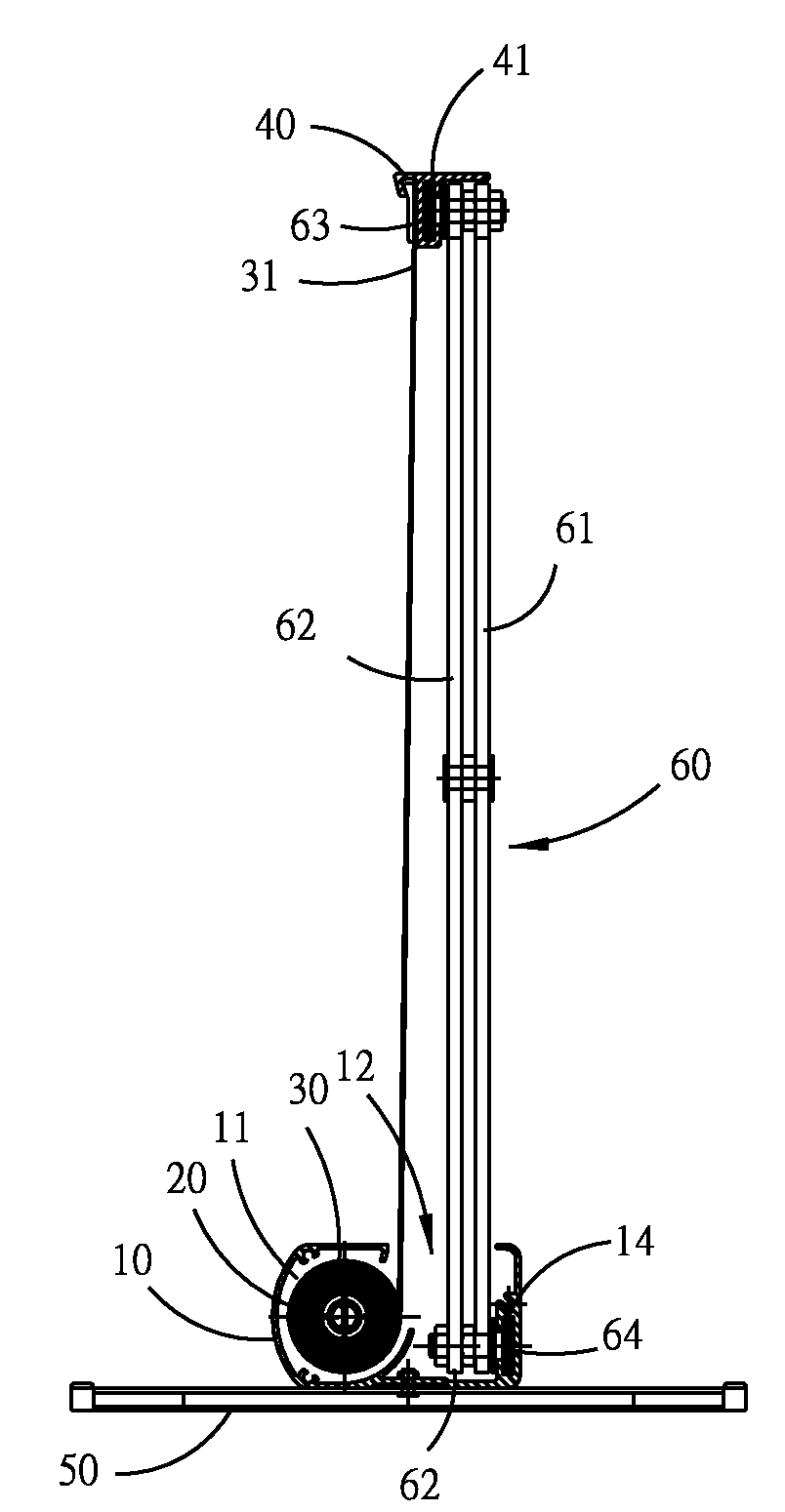
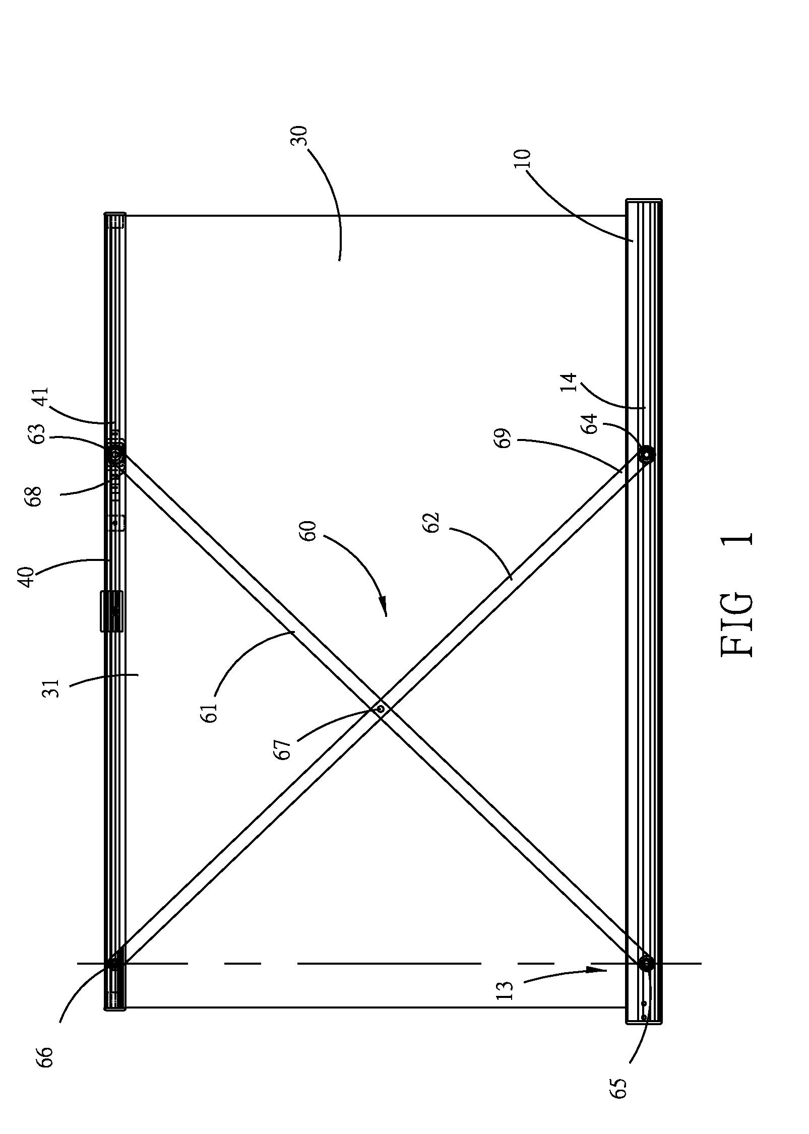
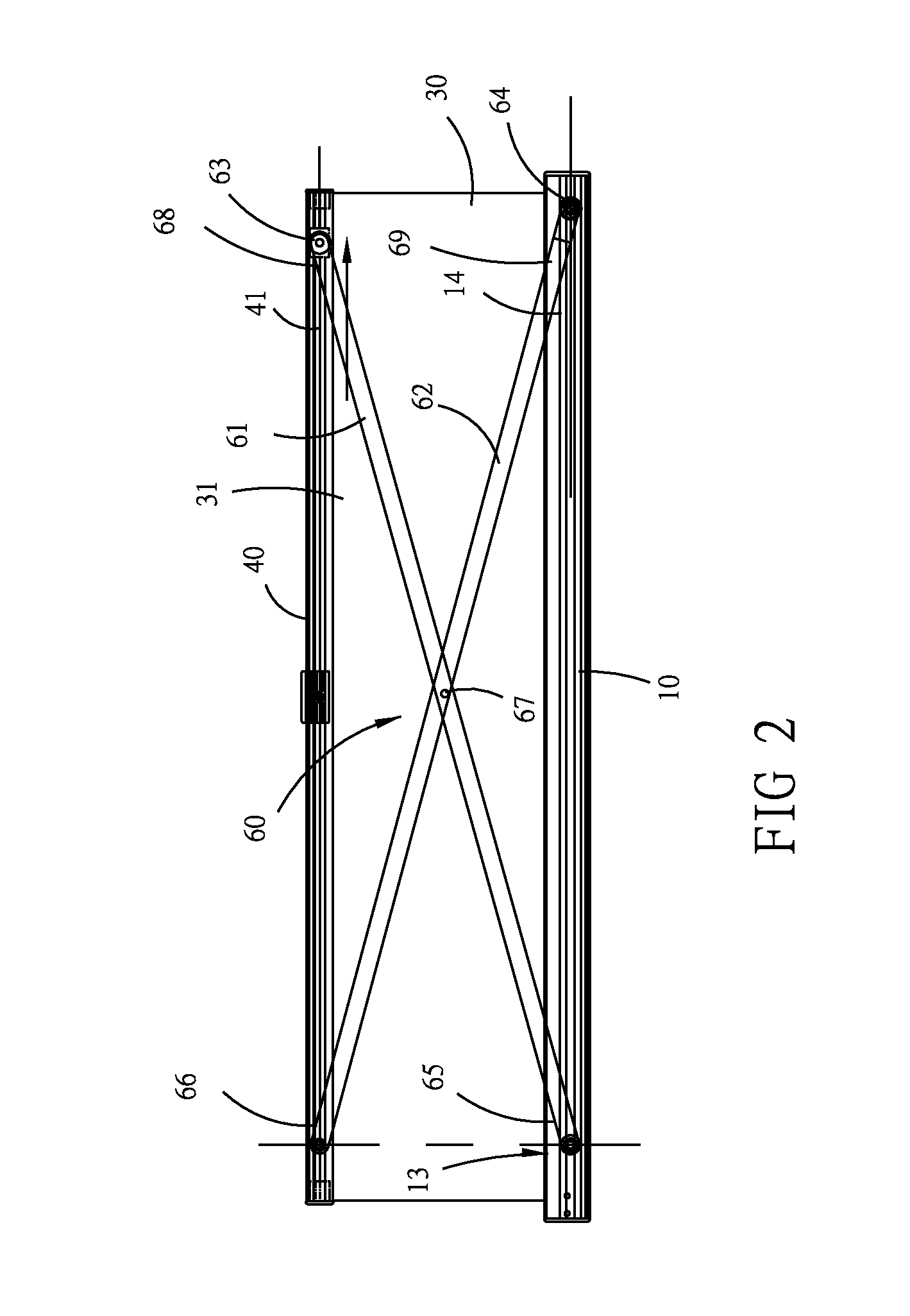
[0023]As shown in FIGS. 1-4, the portable projection screen of the present invention mainly comprises: a first frame 10; a mounting roll 20; a screen 30; a second frame 40; a foot stand group 50; and a lever assembly 60. The first frame 10 is horizontally oriented, made of light and stable aluminum and shaped like a hollow rod, having an interior 11. The mounting roll 20 is disposed along the first frame 10, placed within the interior 11 thereof and is rotatable around a longitudinal axis. The screen 30 has a lower edge, which is connected with the mounting roll 20, and an upper edge, which is a movable edge 31 and is connected with the second frame 40 along a longitudinal extension thereof.

[0024]The mounting roll 20 has a rolling spring (not shown). Unfolding the screen 30 drives the rolling spring. In an unfolded state of the screen 30, the rolling spring is fixed, storing elastic energy, which, for folding the screen 30, drives the screen 30 to be rolled on the mounting roll 20.

[...


PUM


Abstract

A portable projection screen comprises a first frame, a second frame a screen, rolled up within the first frame in a folded state, having a movable end, which is attached to the second frame, and a lever assembly, having two levers which form a shape like the letter X (or double X) with fixed and glidable ends, supporting the second frame in an unfolded state and being accommodated in the first frame in the folded state for a minimized volume and easy portability.

Description

FIELD OF THE INVENTION[0001]The present invention relates to a portable projection screen, particularly to a portable projection screen with a foldable frame for easy portability.BACKGROUND OF THE INVENTION[0002]Conventional projection screens are mostly hanging constructions, each mostly comprising a roll, which is horizontally oriented and suspended on wall, a screen, rolled up on the roll, and a mechanism for rolling and unrolling the screen, which is driven manually or by a motor.[0003]Such projection screens with large screens have high volumes and weights and are usually fixedly installed in classrooms or meeting rooms, without being portable as needed.[0004]There are also portable screens, each of which commonly has a rollable screen and a height-adjustable frame. For opening the screen, the frame is vertically placed on the ground. When the screen is not used, the screen is detached from the frame, the screen is rolled up and the frame is shortened for transporting or storin...

Claims


Application Information

Patent Timeline
Patent Type & Authority Applications(United States)
IPC IPC(8): G03B21/58
CPCG03B21/58
Inventor CHEN, YIN-WEN
Owner CHEN YIN WEN
Why Eureka
Try Eureka