Heat generation inhibiting circuit for exciting coil in relay

a heat generation and inhibiting circuit technology, applied in electromagnetic relays, electrical apparatus, relays, etc., can solve the problems of increasing the size of the pcb substrate, generating power loss, and difficult mounting of the relay circuit on the pcb substrate, so as to reduce the required space, reduce the voltage applied to the exciting coil, and reduce the amount of heat generation

Inactive Publication Date: 2012-06-28
YAZAKI CORP
View PDF4 Cites 4 Cited by
  • Summary
  • Abstract
  • Description
  • Claims
  • Application Information

AI Technical Summary

Benefits of technology

[0037]According to the first invention, since the exciting current flows on the ground side via the diode (D1) until the relay contact is closed immediately after the switch unit is turned on, the voltage applied to the exciting coil is almost same as the power supply voltage. Thus, the relay contact can be surely attracted to switch into the closed state. Further, when the relay contact is closed, since the exciting current flows on the ground side via the first resistor (R1), the voltage applied to the exciting coil reduces and hence the heat generation amount can be reduced. Accordingly, in the case of mounting on a PCB substrate etc., many relay circuits can be mounted on a narrow space, the reduction of a required space and the cost reduction can be realized. Further, since a leak current does not flow in the turned-off state of the switch unit, the power loss can be suppressed.
[0038]According to the second invention, since the exciting current flows on the ground side via the semiconductor element (T1) until the relay contact is closed immediately after the switch unit is turned on, the voltage applied to the exciting coil is almost same as the power supply voltage. Thus, the relay contact can be surely attracted to switch into the closed state. Further, when the relay contact is closed, due to the operation of the semiconductor element, the voltage applied to the exciting coil can be held to the constant voltage depending on the constant voltage of the constant voltage diode. Thus, the heat generation amount can be reduced by setting the voltage applied to the exciting coil to a voltage lower than the power supply voltage. Further, the exciting coil can be energized with a stable voltage without being influenced by the voltage change and the closed state of the relay contact can be surely held. Accordingly, in the case of mounting on a PCB substrate etc., many relay circuits can be mounted on a narrow space, the reduction of a required space and the cost reduction can be realized. Further, since a leak current does not flow in the turned-off state of the switch unit, the power loss can be suppressed.
[0039]According to the third invention, since the diode (D1) is further provided in addition to the configuration of claim 2, until the relay contact is closed immediately after the switch unit is turned on, since the current flows on the ground side via the diode (D1) in addition to the semiconductor element (T1), the voltage applied to the exciting coil can be made close to the power supply voltage.
[0040]According to the fourth invention, since the exciting current flows on the ground side via the semiconductor element (T2) and the diode (D2) until the relay contact is closed immediately after the switch unit is turned on, the voltage applied to the exciting coil is almost same as the power supply voltage. Thus, the relay contact can be surely attracted to switch into the closed state. Further, when the relay contact is closed, since the exciting current does not flow into the semiconductor element (T2) but flows on the ground side via the first resistor (R1), the voltage applied to the exciting coil reduces and hence the heat generation amount can be reduced. Accordingly, in the case of mounting on a PCB substrate etc., many relay circuits can be mounted on a narrow space, the reduction of a required space and the cost reduction can be realized. Further, since a leak current does not flow in the turned-off state of the switch unit, the power loss can be suppressed.
[0041]According to the fifth invention, since the exciting current flows on the ground side via the semiconductor element (T1) until the relay contact is closed immediately after the switch unit is turned on, the voltage applied to the exciting coil is almost same as the power supply voltage. Thus, the relay contact can be surely attracted to switch into the closed state. Further, when the relay contact is closed, due to the operation of the semiconductor element (T1), the voltage applied to the exciting coil can be held to the constant voltage depending on the constant voltage of the constant voltage diode. Thus, the heat generation amount can be reduced by setting the voltage applied to the exciting coil to a voltage lower than the power supply voltage. Further, the exciting coil can be energized with a stable voltage without being influenced by the voltage change and the closed state of the relay contact can be surely held. Accordingly, in the case of mounting on a PCB substrate etc., many relay circuits can be mounted on a narrow space, the reduction of a required space and the cost reduction can be realized. Further, since a leak current does not flow in the turned-off state of the switch unit, the power loss can be suppressed.
[0042]According to the sixth invention, since the battery mounted on a vehicle is used as the DC power supply, the exciting coil can be energized with a stable voltage even when a large voltage change occurs, whereby the relay circuit can be switched safely.

Problems solved by technology

In such the relay circuit, power loss is generated when an exciting coil for exciting a relay contact is supplied with current.
In the case of using the PCB substrate within an engine room of a high ambient temperature, since such the use causes the temperature of various devices mounted on the PCB substrate to exceed the allowable temperature thereof, it becomes difficult to mount may relay circuits on the PCB substrate.
In other words, since the number of the relay circuits capable of being mounted on the PCB substrate is restricted, the size of the PCB substrate becomes large.
Thus, there is a limit in the method of reducing the heat generation amount of the exciting coil Xc by increasing the resistance value Ra.

Method used


Image

  • Heat generation inhibiting circuit for exciting coil in relay
  • Heat generation inhibiting circuit for exciting coil in relay
  • Heat generation inhibiting circuit for exciting coil in relay

Examples


first embodiment

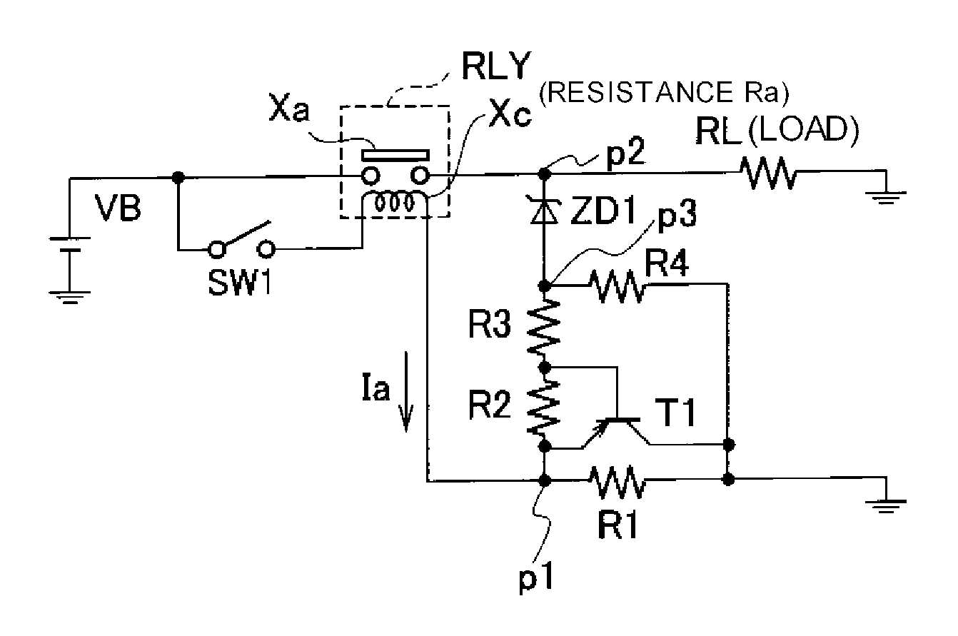
[0052]FIG. 1 is a circuit diagram showing the configuration of a load driving circuit on which a heat generation inhibiting circuit according to the first embodiment of this invention is mounted. As shown in FIG. 1, the load driving circuit includes a load RL such a lamp and a motor mounted on a vehicle, for example, and a DC power supply VB (for example, a battery, hereinafter abbreviated as “power supply VB”), and a relay circuit RLY is provided between the power supply VB and the load RL. The output voltage of the power supply VB is shown by the same symbol VB. This output voltage is 14 volt, for example.

[0053]The relay circuit RLY includes a normally-opened relay contact Xa and an exciting coil Xc. The one end of the relay contact Xa is connected to the positive electrode terminal of the power supply VB and the other end thereof is grounded via the load RL. The resistance value of the exciting coil Xc is Ra. The one end of the exciting coil Xc is connected to the positive electr...

second embodiment

Modified Example of Second Embodiment

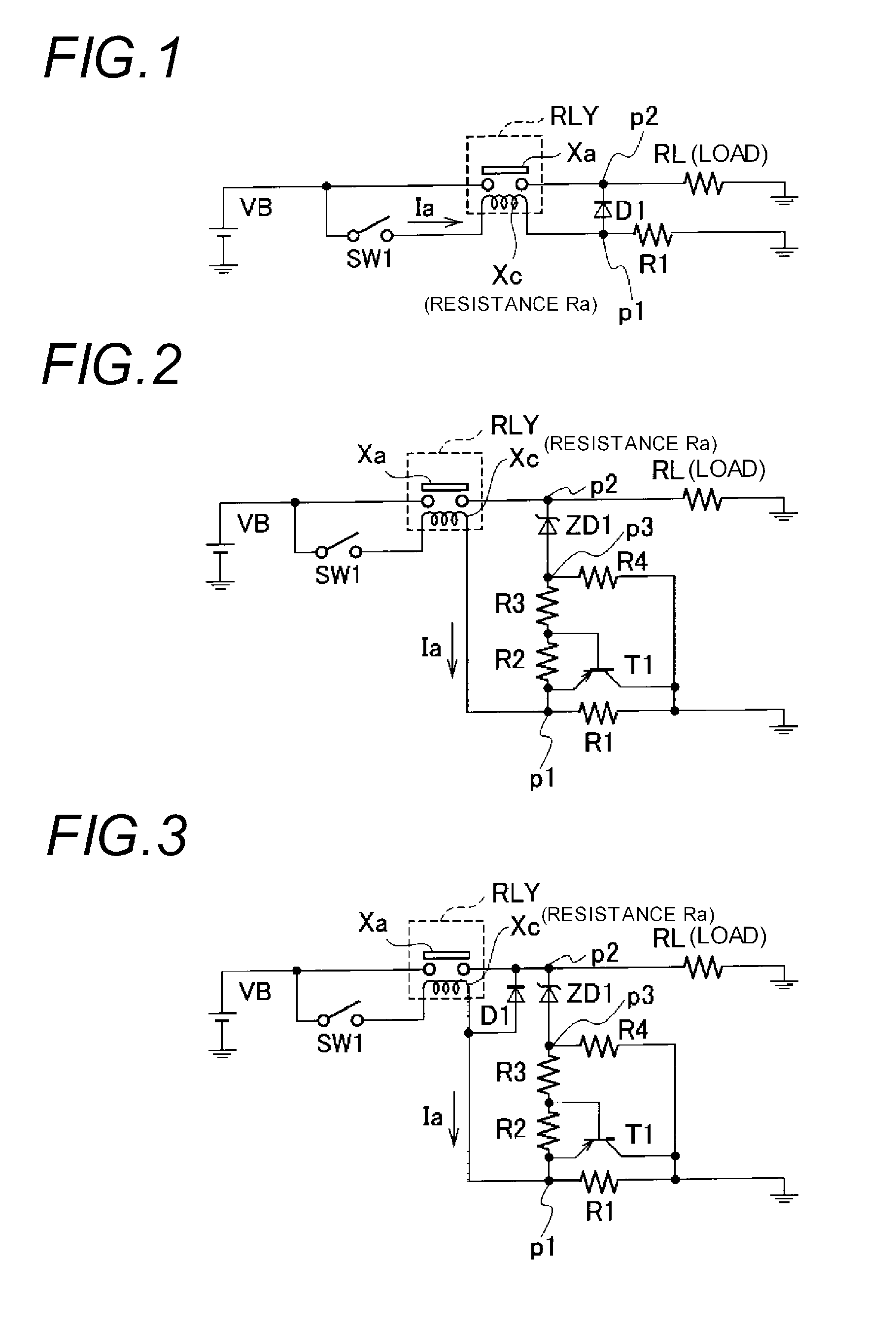
[0076]Next, the heat generation inhibiting circuit according to the modified example of the second embodiment will be explained. FIG. 3 is a circuit diagram showing the configuration of a load driving circuit on which the heat generation inhibiting circuit according to the modified example is mounted. As shown in FIG. 3, this load driving circuit differs from the circuit shown in FIG. 2 in a point that the diode D1 is provided. That is, the diode D1 is provided in a manner that the anode thereof is connected to the connection point p1 between the exciting coil Xc and the resistor R1 and the cathode thereof is connected to the connection point p2 between the relay contact Xa and the load RL.

[0077]In the heat generation inhibiting circuit thus configured, during a period that the relay contact Xa is opened after the switch SW1 is turned on, since the exciting current Ia flowing into the exciting coil Xc flows from the diode D1 to the ground via the...

third embodiment

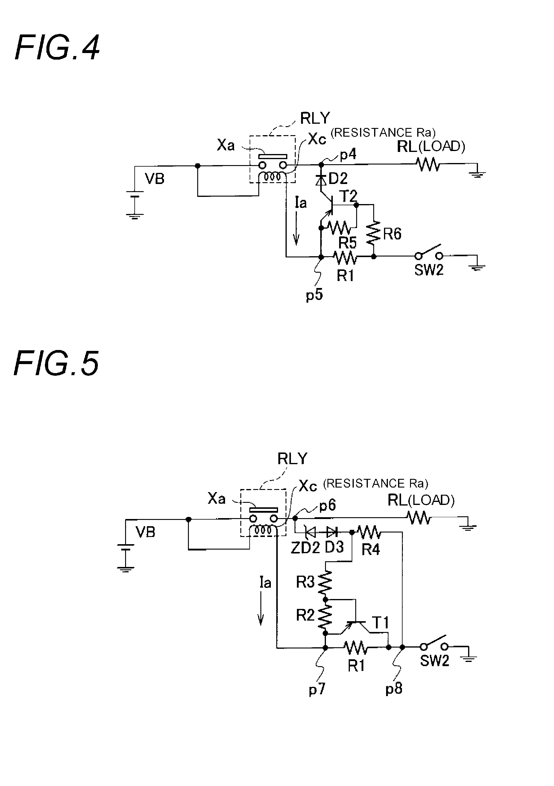
[0078]Next, the third embodiment of this invention will be explained. FIG. 4 is a circuit diagram showing the configuration of a load driving circuit on which the heat generation inhibiting circuit according to the third embodiment of this invention is mounted. As shown in FIG. 4, this load driving circuit includes the load RL such a lamp and a motor and the power supply VB (for example, a battery), and the relay circuit RLY is provided between the power supply VB and the load RL.

[0079]The relay circuit RLY includes the normally-opened relay contact Xa and the exciting coil Xc. The one end of the relay contact Xa is connected to the positive electrode terminal of the power supply VB and the other end thereof is grounded via the load RL. The one end of the exciting coil Xc is connected to the positive electrode terminal of the power supply VB and the other end thereof is grounded via the resistor R1 (first resistor) and a switch SW2 (switch unit). That is, the third embodiment differ...


PUM


Abstract

A resistor is provided between an exciting coil and the ground, and a diode is provided between a point p1 and a point p2. An exciting current flows on the ground side via the diode until a relay contact is closed immediately after a switch is turned on. Thus, a voltage applied to the exciting coil becomes almost same as a power supply voltage, the relay contact can be surely closed. Further, when the relay contact is closed, since the exciting current flows on the ground side via the resistor the voltage applied to the exiting coil reduces and hence the heat generation amount can be reduced.

Description

TECHNICAL FIELD[0001]The present invention relates to a heat generation inhibiting circuit for inhibiting the heat generation of an exciting coil provided in a relay circuit.BACKGROUND ART[0002]For example, a relay circuit for controlling the driving and stop of various kinds of loads such as a lamp and a motor mounted on a vehicle is used in a state of being mounted on a PCB substrate. In such the relay circuit, power loss is generated when an exciting coil for exciting a relay contact is supplied with current. The power loss is converted into heat energy to increase the temperature of the PCB substrate. In the case of using the PCB substrate within an engine room of a high ambient temperature, since such the use causes the temperature of various devices mounted on the PCB substrate to exceed the allowable temperature thereof, it becomes difficult to mount may relay circuits on the PCB substrate. In other words, since the number of the relay circuits capable of being mounted on the...

Claims


Application Information

Patent Timeline
Patent Type & Authority Applications(United States)
IPC IPC(8): H01H47/00
CPCH01H47/10H01H47/32H01H47/26H01H47/22
Inventor OHSHIMA, SHUNZOU
Owner YAZAKI CORP
Why Eureka
Try Eureka