Vehicle drive system

a technology of drive system and clutch, which is applied in the direction of mechanical energy handling, mechanical apparatus, clutches, etc., can solve the problem of ineffective utilization of oil inside the cover body, and achieve the effect of smooth oil flow

Inactive Publication Date: 2012-08-30
AISIN AW CO LTD
View PDF0 Cites 12 Cited by
  • Summary
  • Abstract
  • Description
  • Claims
  • Application Information

AI Technical Summary

Benefits of technology

[0029]According to the eighth aspect of the present invention, the rotation sensor is not disposed on the first axial direction side of the rotor support member on which the opposing extension surface...

Problems solved by technology

However, the art in WO 2005/105507 uses a configuration in which oil is not supplied from outside to the rotor support bearing, and the type of bearing that can be used as the rotor support beari...

Method used


Image

  • Vehicle drive system
  • Vehicle drive system
  • Vehicle drive system

Examples


first embodiment

1. First Embodiment

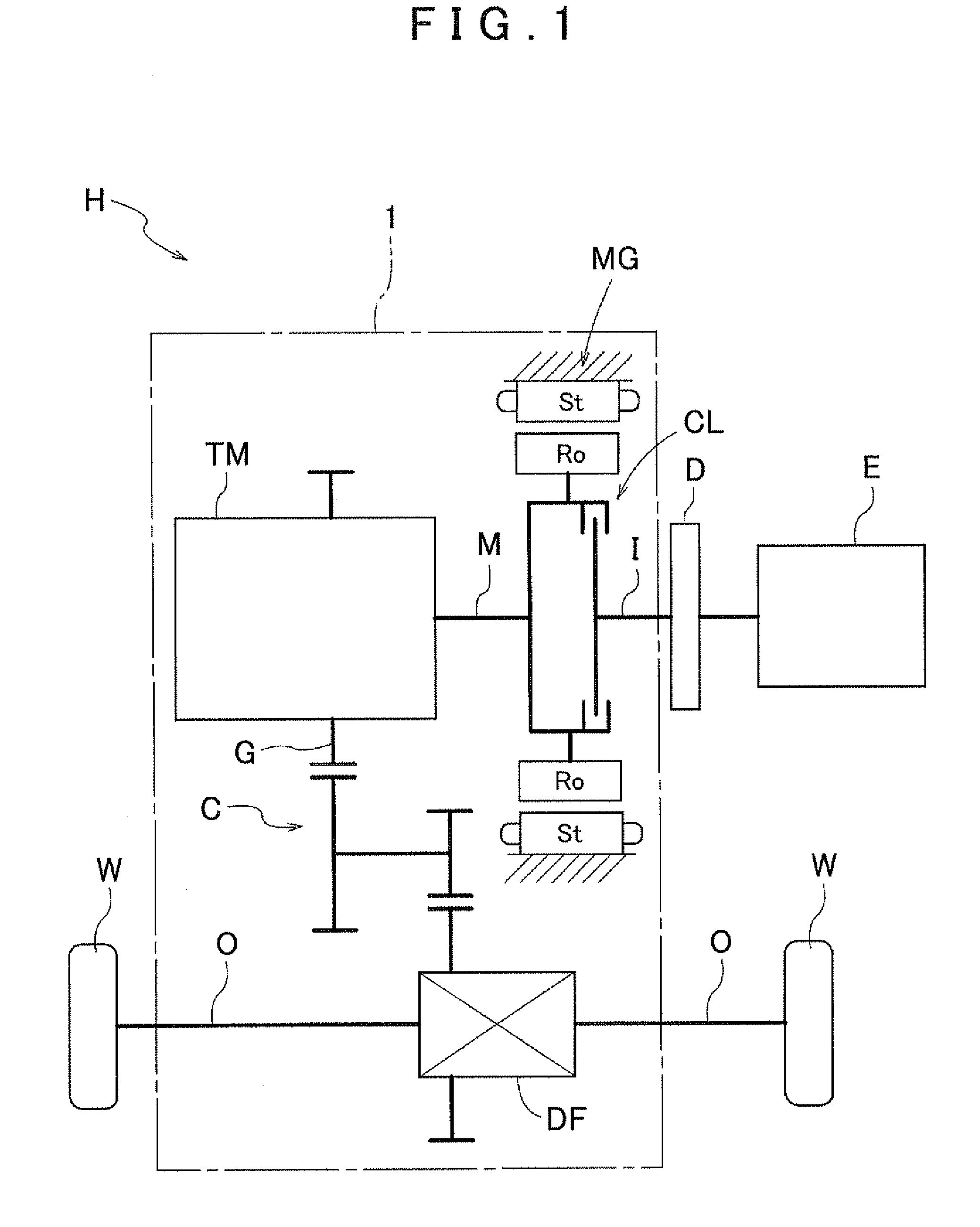
[0035]An embodiment of the present invention will be described with reference to the drawings. In the present embodiment, a vehicle drive system according to the present invention is applied as a hybrid drive system as an example. FIG. 1 is a schematic diagram that shows the overall configuration of a hybrid drive system H according to the present embodiment. The hybrid drive system H is a drive system for a hybrid vehicle that uses one or both of an internal combustion engine E and a rotating electric machine MG as a drive power source of the vehicle. The hybrid drive system H is configured as a so-called one-motor parallel type of hybrid drive system. The hybrid drive system H according to the present embodiment will be described in detail below.

1-1. Overall Configuration of Hybrid Drive System

[0036]First, the overall configuration of the hybrid drive system H according to the present embodiment will be described. As shown in FIG. 1, the hybrid drive system H in...


PUM


Abstract

A vehicle drive system includes a rotor support that is more radially inward than the stator and supports the rotor; a supply that supplies oil to the rotor support bearing, the rotor support bearing includes a discharge that discharges oil supplied from the supply, the rotor support includes an opposing surface that opposes the discharge-side surface, and an opposing extension surface that extends radially from the opposing surface. The stator includes a coil end that protrudes from the stator core toward the first axial direction. A radial outer end of the opposing extension surface is more radially inward than, and overlaps with, the coil end, with a radial space between the radial outer end and the coil end. The discharge-side surface is disposed more toward the second axial direction than the radial outer end of the opposing extension surface.

Description

INCORPORATION BY REFERENCE[0001]The disclosure of Japanese Patent Application No. 2011-042101 filed on Feb. 28, 2011 including the specification, drawings and abstract is incorporated herein by reference in its entirety.BACKGROUND OF THE INVENTION[0002]The present invention relates to a vehicle drive system that includes, as a drive power source of a vehicle, a rotating electric machine that has a rotor and a stator.Description of the Related Art[0003]Art such as that disclosed in WO 2005 / 105507 Pamphlet below relates to the vehicle drive system described above. In the vehicle drive system according to WO 2005 / 105507, a case (motor housing 4) includes a radially extending support wall (partition member 50) on one side of the axial direction of a rotating electric machine (motor generator 2), and a rotor support member (rotor support plate 41 and front cover 24) that rotatably supports a rotor (40). A rotor support bearing (bearing 55) is disposed between the support wall and the rot...

Claims


Application Information

Patent Timeline
IPC IPC(8): H02K9/193
CPCH02K7/006H02K11/0015H02K9/19H02K7/083H02K11/21F16D25/0638F16D25/123
Inventor KASUYA, SATORUKITO, MASASHISUGISAKA, SHIGERUMORI, HIDEYUKI
Owner AISIN AW CO LTD
Why Eureka
Try Eureka