Exhaust type oil outlet device with built-in oil tanks

An oil outlet and oil tank technology, applied in locomotives and other directions, can solve problems such as reducing use efficiency, prolonging oil injection time, delaying construction period, etc., to facilitate monitoring and maintenance, improve oil injection quality, and eliminate potential safety hazards.

Inactive Publication Date: 2012-11-07
CRRC BEIJING ERQI VEHICLE CO LTD
View PDF6 Cites 0 Cited by
  • Summary
  • Abstract
  • Description
  • Claims
  • Application Information

AI Technical Summary

Problems solved by technology

However, since the assembled fuel tank and the ventilation pipe between each fuel tank and other devices have been sealed in the side beam of the car body, its use status cannot be observed from the outside. When the ventilation pipe is not smooth, the built-in fuel tank will not enter the oil smoothly. It is very slow, and even oil spills may occur, which prolongs the oil filling time, reduces the efficiency of use, and delays the construction period
When the air pipe is blocked, the built-in fuel tank cannot be filled with oil. Sometimes, in order to speed up the oil filling, holes are even drilled at the upper cover plate of the closed car body side beam steel structure to allow air to circulate. Transportation and construction operations have brought great potential safety hazards

Method used


Image

  • Exhaust type oil outlet device with built-in oil tanks
  • Exhaust type oil outlet device with built-in oil tanks
  • Exhaust type oil outlet device with built-in oil tanks

Examples


Embodiment Construction

[0014] The present invention will be described in detail below in conjunction with the accompanying drawings and embodiments.

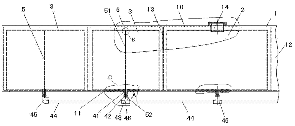
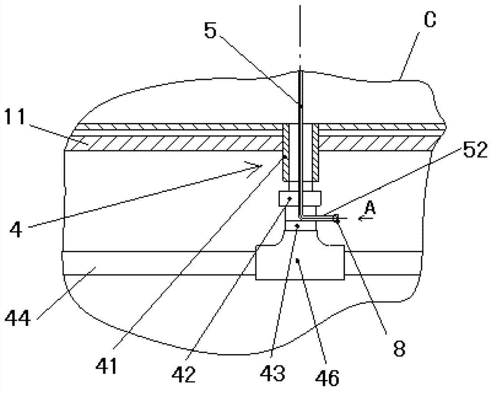
[0015] Such as figure 1 , figure 2 As shown, the present invention includes a closed structure 1, a built-in main fuel tank 2 and several built-in auxiliary fuel tanks 3; the closed structure 1 is formed by welding an upper cover plate 10, a lower cover plate 11, two webs 12 and several partitions 13 A number of independent enclosed structural spaces, in which a built-in main fuel tank 2 or a built-in auxiliary fuel tank 3 is placed as required, and the top of the built-in main fuel tank 2 is provided with an oil filling port 14 communicating with the upper cover plate 10 of the closed structure 1, The bottom of the built-in main oil tank 2 and each built-in auxiliary oil tank 3 are respectively provided with an oil outlet communicating with the lower cover plate 11 of the closed structure 1, and an oil outlet device 4 is arranged at each oil outlet...


PUM


Abstract

The invention relates to an exhaust type oil outlet device with built-in oil tanks. The exhaust type oil outlet device is characterized by comprising a closed structure body, built-in main oil tanks and built-in auxiliary oil tanks. The closed structure body comprises a plurality of independent closed structure spaces, the built-in main oil tanks and the built-in auxiliary oil tanks are arranged in the independent closed structure spaces, the bottoms of the built-in main oil tanks and the bottoms of built-in auxiliary oil tanks are respectively provided with oil outlets, and an oil outlet device body is arranged at the positions of the oil outlets. The oil outlet device body comprises oil outlet tubes, one end of each oil outlet tube is fixedly welded with the oil outlets, the other end of each oil outlet tube is connected with tube connectors, transition oil tubes are fixedly welded at the bottoms of the tube connectors, connecting devices are fixedly welded at the bottoms of the transition oil tubes, and oil transporting tubes are arranged among adjacent connecting devices. L-shaped air leading tubes are arranged in the built-in auxiliary oil tanks, the long ends of the L-shaped air leading tubes are located inside the built-in auxiliary oil tanks, and the short ends of the L-shaped air leading tubes extend out of the tube connectors to be communicated with the outside through inverted U-shaped openings arranged at the bottoms of the tube connectors. The exhaust type oil outlet device with the built-in oil tanks can be widely applied to a structure for placing built-in oil tanks pf the full-closed structure, especially can be applied to a built-in oil tank structure of a flatcar for a railway track-laying machine and a bridging unit.

Description

technical field [0001] The invention relates to an oil outlet device, in particular to an exhaustable oil outlet device with a built-in oil tank. Background technique [0002] The built-in fuel tank refers to the fuel tank placed in a fully enclosed structure. For example, a built-in fuel tank is installed in the side beam of the car body of the flat car used for railway track laying machines and bridge erecting units to provide reserve oil for the whole machine to run independently. This detachable The independent built-in oil tank realizes the need to provide reserve oil for the operation of the track laying machine and bridge erecting machine. However, since the fuel tank after assembly and the ventilation pipes between each fuel tank and other devices have been sealed in the side beam of the car body, its use status cannot be observed from the outside. When the ventilation pipe is not smooth, the internal fuel tank will not enter the oil smoothly. It is very slow, and e...

Claims


Application Information

Patent Timeline
Patent Type & Authority Applications(China)
IPC IPC(8): B61C17/02
Inventor 黄元琳马国英
Owner CRRC BEIJING ERQI VEHICLE CO LTD
Why Eureka
Try Eureka