
Extrusion Device

Inactive Publication Date: 2012-09-06
HILTI AG
View PDF4 Cites 0 Cited by
  • Summary
  • Abstract
  • Description
  • Claims
  • Application Information

AI Technical Summary

Benefits of technology

[0006]A problem addressed by one or more embodiments of the invention is that of providing an extrusion device for extruding mate

Problems solved by technology

However, these advancement devices have the disadvantage that it is only possible to extrude the material in the cartridge in a step-wise manner, because in order to change the position of the clamp element on the plunger rod, the advancement device must be completely disengaged each time.
Such an advancement mechanism, however, has the disadvantage that the traction mechanism must be stowed inside the housing and takes up more space when fully rolled up around the spool.
In configurations wherein the traction mechanism is coiled in coil paths which are adjacent to each other, undesired shear forces are exerted on the plunger rod due to the changing skew of the traction mechanism.
These shear forces can lead to a canting or deformation of the plunger rod.

Method used


Image

  • Extrusion Device
  • Extrusion Device
  • Extrusion Device

Examples


Embodiment Construction

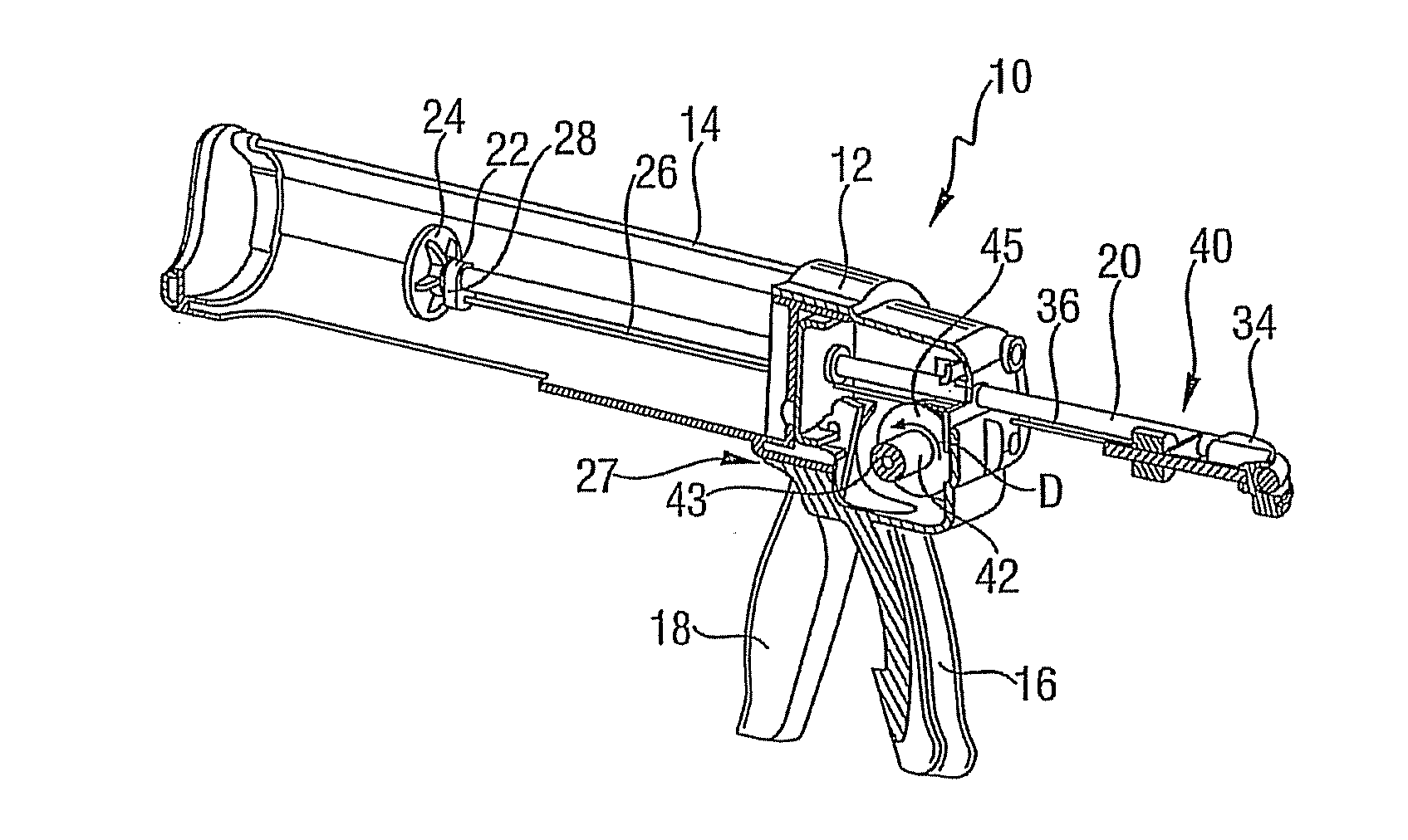
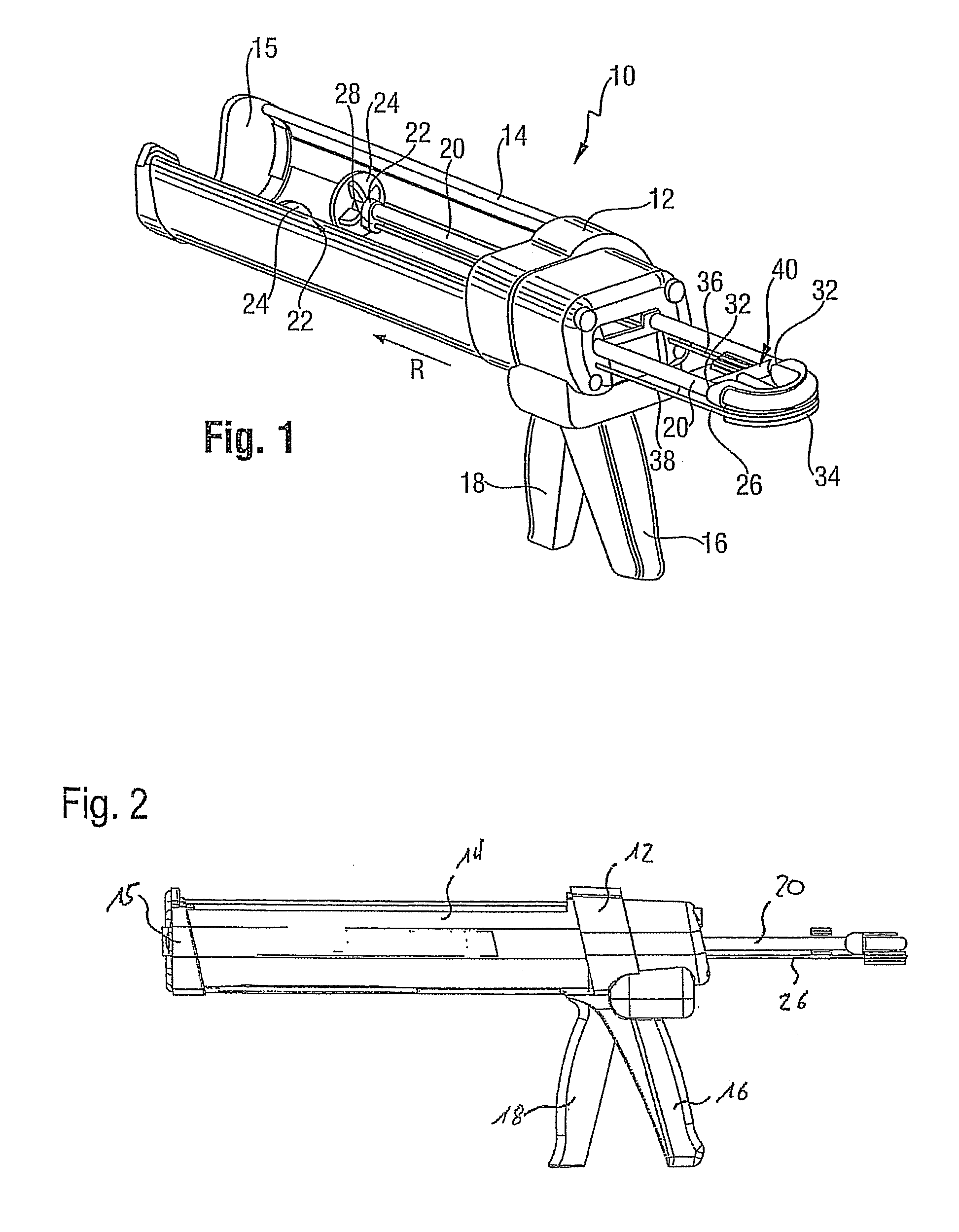
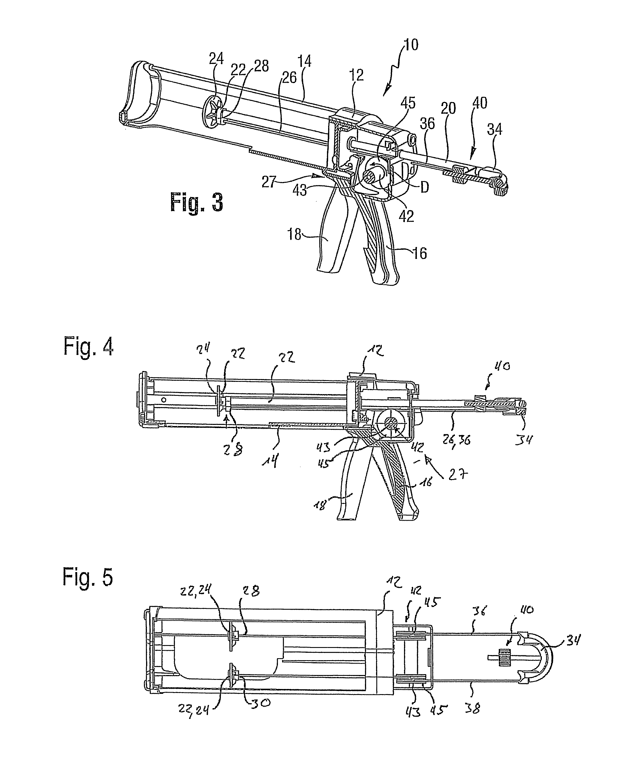
[0015]One or more embodiments of the present invention provide an extrusion device for extruding the material in a cartridge, having at least one movable plunger rod, at least one bendable traction element which is coupled to the plunger rod or plunger rods on attachment points thereof, and having an advancement device which is coupled to the traction element between the attachment points and which actuates the movement of the plunger rod. The advancement device has at least one driven rotating body, and the traction element is wound around said rotating body between the attachment points thereof. The rotating body drives the traction device. Due to the winding, the traction mechanism is always partially wound around the rotating body at a constant angle of wrap. No shear forces are present, and the movement of the plunger rod is always constant.

[0016]The traction element is preferably tensioned between both attachment points, meaning around the rotating body, and the rotating body ...


PUM


Abstract

An extrusion device for extruding material from cartridges, having at least one plunger rod which can be moved, at least one bendable traction element which is coupled to the plunger rod(s) at attachment points, and having an advancement device which is coupled to the traction element between the attachment points and which actuates the movement of the plunger rod, wherein the advancement device has at least one driven rotating body, the traction element being wound around the same between its attachment points, and being driven by the same.

Description

CROSS-REFERENCE TO RELATED APPLICATIONS[0001]The present application claims priority to German Patent Application DE 10 2011 004 254.7, filed Feb. 16, 2011, and entitled “Auspressgerat” (“Extrusion Device”), which is hereby incorporated by reference in its entirety.BACKGROUND OF THE INVENTION[0002]The present invention relates to an extrusion device for extruding material from cartridges, having at least one plunger rod which can be moved.[0003]Such extrusion devices are used in construction applications, for example, for extruding material from cartridges which are filled with silicone or other liquid and / or semiliquid construction materials. These cartridges typically have a cylindrical body with a discharge opening arranged on one end wall. The opposite end wall is formed by a male element which can travel inside the cylindrical body, such that the volume of the cartridge can be modified using the movement of this end wall, and as a result the contents of the cartridge can be pre...

Claims


Application Information

Patent Timeline
IPC IPC(8): B67D7/60
CPCB05C17/00B05C17/0109B05C17/0116B05C17/00596B05C17/00553B05C17/0103B05C17/0123
Inventor HEFELE, CHRISTIAN
Owner HILTI AG
Learn More