Stacked integrated component devices with energization

a technology of integrated components and components, applied in the direction of electrical equipment construction details, instruments, other domestic objects, etc., can solve the problems of unfavorable size and power requirements of available discrete devices

Active Publication Date: 2012-09-20
JOHNSON & JOHNSON VISION CARE INC
View PDF34 Cites 151 Cited by
  • Summary
  • Abstract
  • Description
  • Claims
  • Application Information

AI Technical Summary

Problems solved by technology

The topology and size of the space defined by the lens structure creates a novel and challenging environment for the definition of various functionality.
However, the size and power requirements for available discrete devices are not necessarily conducive for inclusion in a device to be worn on a human eye.

Method used


Image

  • Stacked integrated component devices with energization
  • Stacked integrated component devices with energization
  • Stacked integrated component devices with energization

Examples


Embodiment Construction

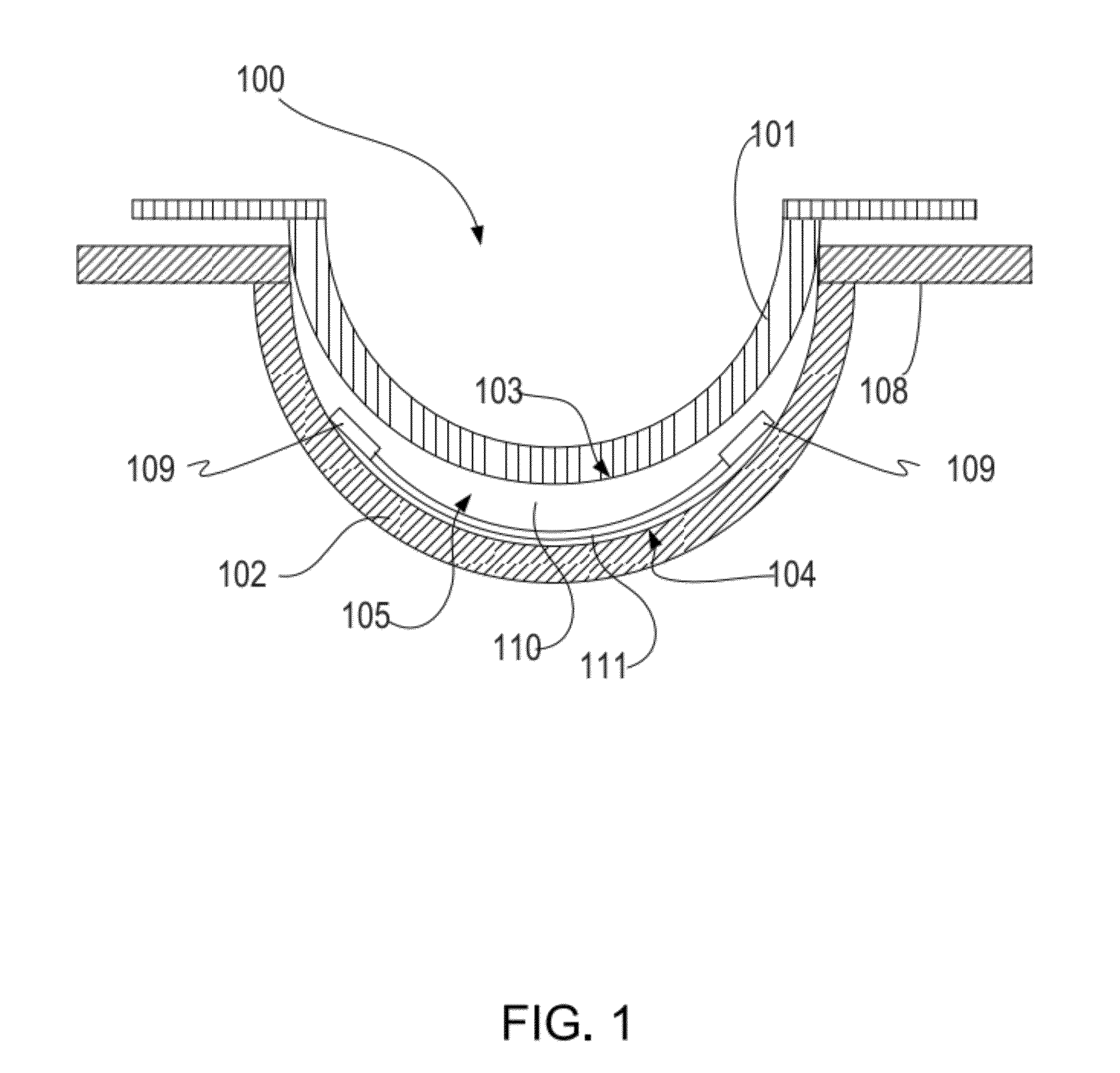
[0023]The present invention includes a substrate insert device formed through the stacking of multiple functionalized layers. Additionally the present invention includes methods and apparatus for manufacturing an ophthalmic lens with such a stacked functionalized layer substrate as an insert in the formed lens. In addition, some embodiments of the present invention include an ophthalmic lens with a stacked functionalized layer substrate insert incorporated into the ophthalmic lens.

[0024]In the following sections detailed descriptions of embodiments of the invention will be given. The description of both preferred and alternative embodiments are exemplary embodiments only, and it is understood that to those skilled in the art that variations, modifications and alterations may be apparent. It is therefore to be understood that said exemplary embodiments do not limit the scope of the underlying invention.

GLOSSARY

[0025]In this description and claims directed to the presented invention, ...


PUM


Abstract

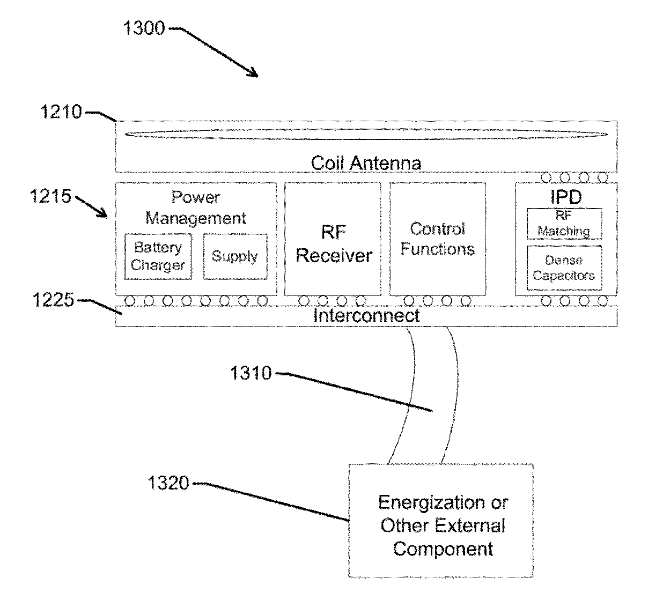
This invention discloses a device comprising multiple functional layers formed on substrates, wherein at least one functional layer comprises an electrical energy source. In some embodiments, the present invention includes a component for incorporation into ophthalmic lenses that has been formed by the stacking of multiple functionalized layers.

Description

RELATED APPLICATIONS[0001]This application claims priority to U.S. Provisional Application Ser. No. 61 / 454,205 filed on Mar. 18, 2011; and U.S. Provisional Application Ser. No. 61 / 454,591 filed on Mar. 21, 2011; the contents of which are relied upon and incorporated by reference.FIELD OF USE[0002]This invention describes a device formed from multiple functional layers which are stacked, wherein at least one layer includes a power source as well as, in some embodiments, methods and apparatus for the fabrication of a stacked integrated component device based on multiple stacked layers.BACKGROUND[0003]Traditionally an ophthalmic device, such as a contact lens, an intraocular lens or a punctal plug included a biocompatible device with a corrective, cosmetic or therapeutic quality. A contact lens, for example, may provide one or more of: vision correcting functionality; cosmetic enhancement; and therapeutic effects. Each function is provided by a physical characteristic of the lens. A de...

Claims


Application Information

Patent Timeline
Patent Type & Authority Applications(United States)
IPC IPC(8): H05K7/06
CPCH01L2224/48091G02B1/043H01L2924/3025H01L2924/01047H01L2924/1461H01L2224/45147H01L2224/48145B29D11/00826H01L2924/01015G02C7/04G02C7/083H01L25/16H01L2924/10253H01L2924/00014H01L2924/00H01L2224/45139H01L2924/00011B29D11/00038H01L2924/01033H01L2924/00012H01L2924/01049G02C7/02
Inventor PUGH, RANDALL B.FLITSCH, FREDERICK A.OTTS, DANIEL B.RIALL, JAMES DANIELTONER, ADAM
Owner JOHNSON & JOHNSON VISION CARE INC
Why Eureka
Try Eureka