
Multi-Outlet Check Valve Nozzle

a check valve and multi-outlet technology, applied in the field of multi-outlet check valves, can solve the problem of limited mixing ability of the check valve nozzles

Active Publication Date: 2012-10-04
RED VALVE
View PDF25 Cites 15 Cited by
  • Summary
  • Abstract
  • Description
  • Claims
  • Application Information

AI Technical Summary

Benefits of technology

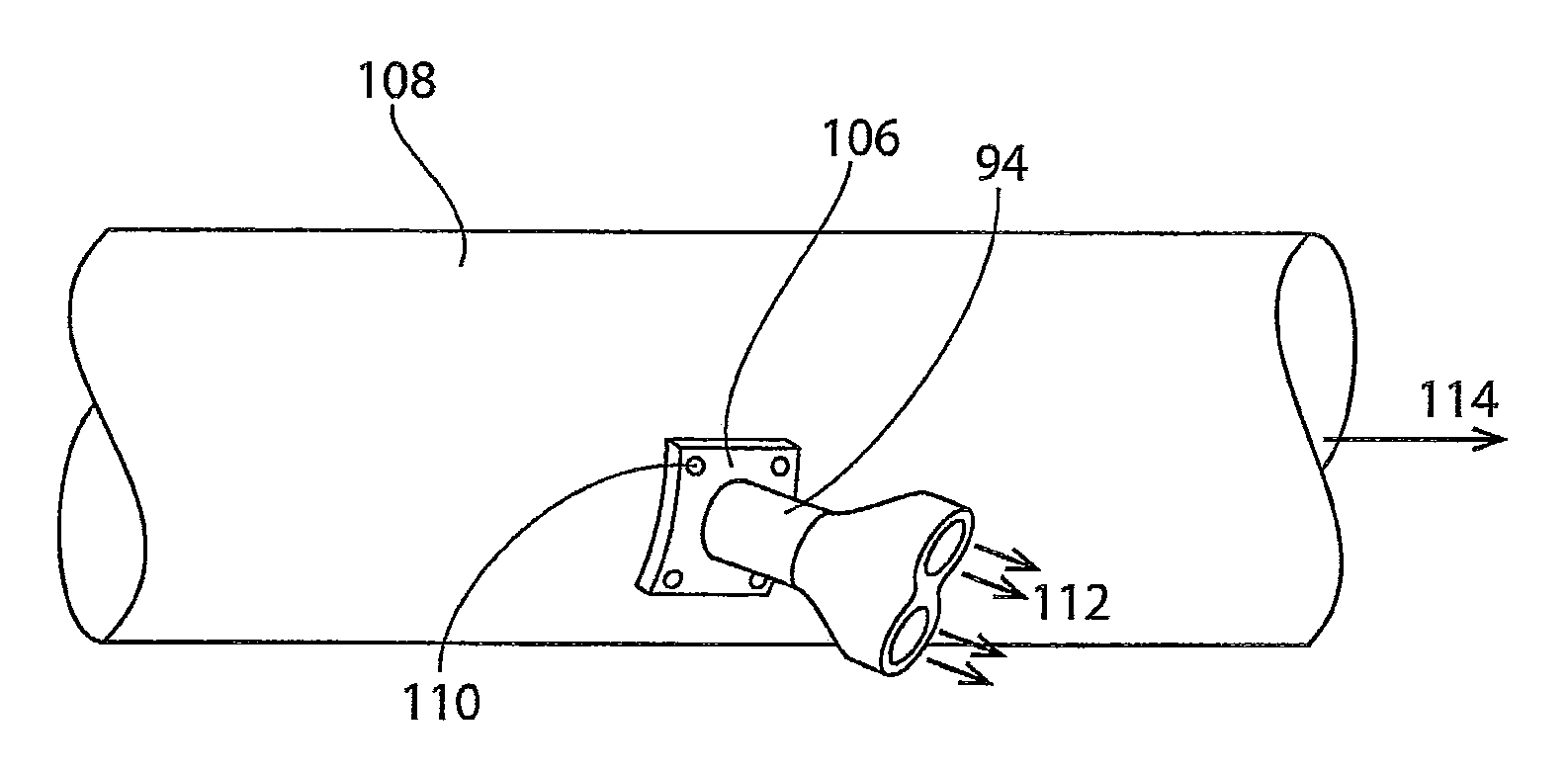
[0010]In another embodiment, the present invention is a “pancake” type check valve nozzle comprising a back plate comprising a disc containing a central bore and having a top face and a bottom face; a cuff comprising a flange and an inlet conduit where the flange is attached to the bottom face of the back plate around the entire periphery of the flange to form a leak proof seal; a front plate attached to the top face of the back plate in at least two places around the periphery of the back plate; and at least two discharge ports formed where the front plate is not attached to the back plate, wherein the fluid flowing through the inlet portion of the cuff will discharge through the discharge ports. At least one of the front plate or the back plate is flexible and may be made of an elastomeric material or a reinforced elastomeric material. The back plate, front plate, and cuff may be concave or convex to direct flow in a forward or rearward direction, respectively.
[0011]In addition, the present invention is directed to

Problems solved by technology

While traditional “duckbill” check valve nozzles have found use as mixing nozzles, their mixing ability is limited.

Method used


Image

  • Multi-Outlet Check Valve Nozzle
  • Multi-Outlet Check Valve Nozzle
  • Multi-Outlet Check Valve Nozzle

Examples


first embodiment

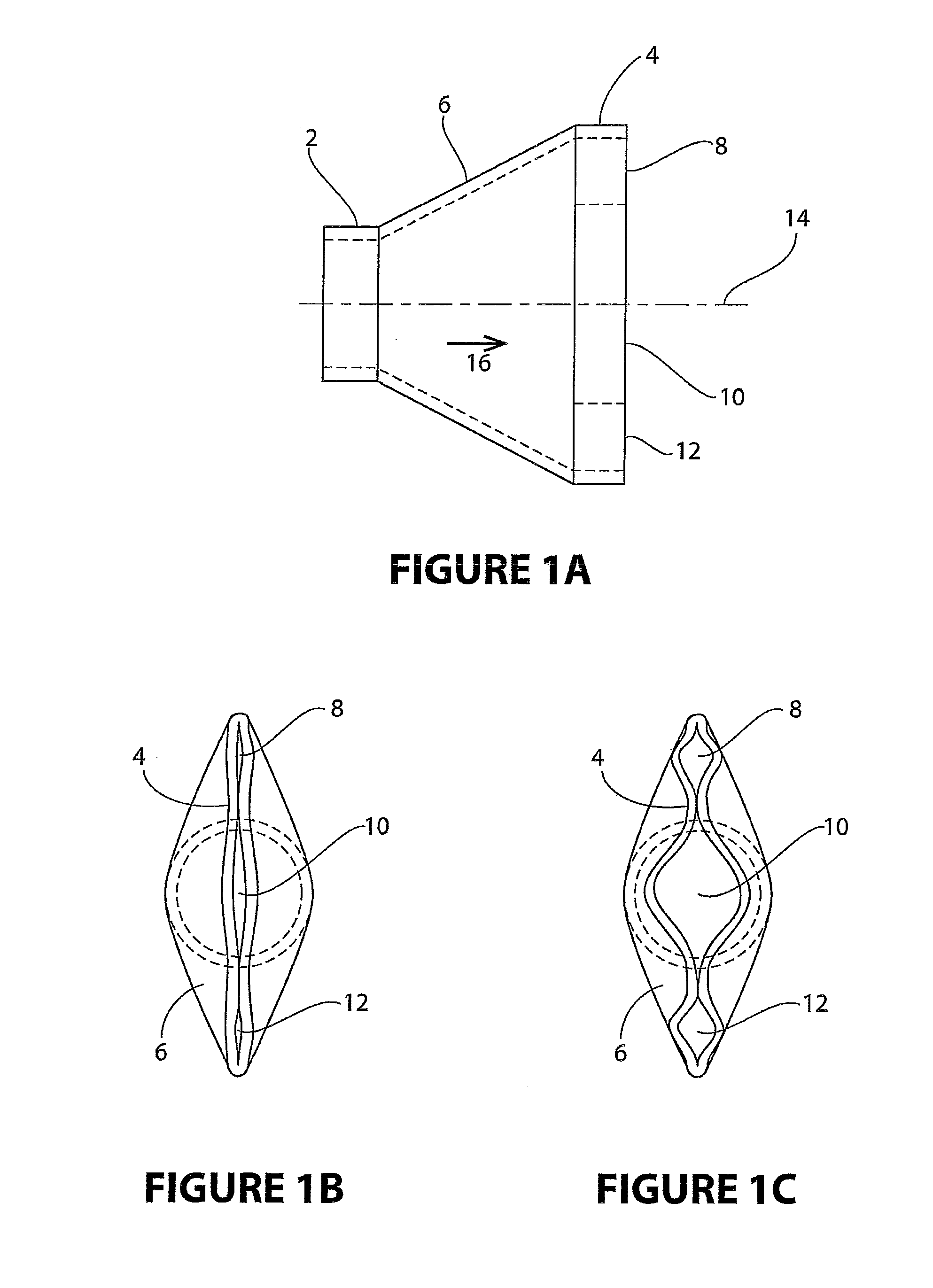
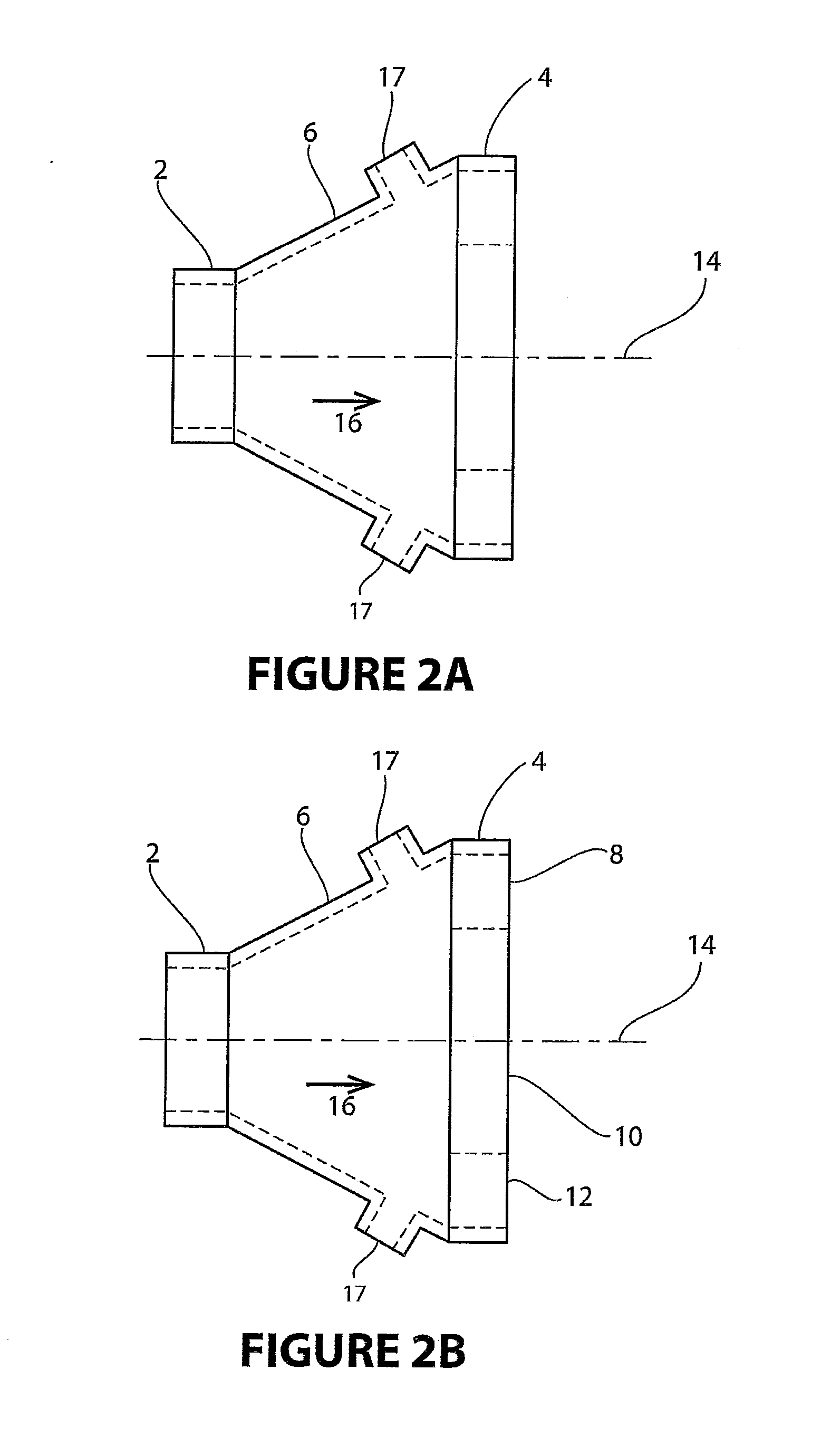
[0049]FIG. 3 shows an alternative configuration of the Two of the three discharge ports 18, 20 are shown placed at an outward angle 22 from the longitudinal centerline 14 of the check valve nozzle. This directs the flow from these two ports in a direction away from the primary flow 16 while the flow through discharge port 24, which is at a 0 degree angle to the longitudinal centerline 14, remains directed in the direction of the primary flow 16. This configuration has advantages in situations where the receiving fluid is contained in a relatively small enclosure, such as a potable water tank, where the discharge from the angled discharge ports 18, 20 can be redirected off the sidewalls of the containment vessel to increase turbulence and improve mixing.

[0050]While FIG. 3 shows two ports 18, 20 oriented at the same outward angle 22 and one port 24 remaining oriented in the direction of primary flow 16, any of the discharge ports may be oriented at any outward angle from the longitud...

second embodiment

[0057]the present invention is a “pancake” type check valve nozzle shown in FIGS. 10A-10C. The check valve nozzle has a back plate 54 which is a disc containing a central bore 58. A circular cuff 60 is attached to the bottom face 62 of the back plate 54. The cuff 60 has a flange 64 and an inlet conduit 66. The flange 64 is attached to one end of the inlet conduit 66 and extends away from the sidewalls of the inlet conduit 66. The other end of the inlet conduit 66 is mountable on a discharge conduit. The flange 64 of the cuff 60 is attached around its entire periphery to the bottom face 62 of the back plate 54 to form a leak proof seal. The flange 64 of the cuff 60 may also be molded or fabricated as an integral part of the back plate 54. A circular front plate 68 is preferably the same size as the back plate 54 and is attached to the top face 70 of the back plate 54 in at least two locations 71 near the periphery of the back plate 54, leaving at least two areas where the front plate...

third embodiment

[0063]the present invention is a check valve nozzle assembly shown in FIGS. 14A-14C. The check valve nozzle assembly has an end cap 75 mountable on the discharge end of a conduit. The end cap 75 has an upstream inlet portion 76 that is mountable on a discharge conduit and a downstream outlet portion 78. The outlet portion 78 contains at least two discharge outlets 80. Check valve nozzles 82 comprising an upstream inlet 84, a downstream outlet portion 86, and a transition portion 88 between the upstream inlet 84 and the downstream outlet portion 86 are attached to the end cap 75. The inlet 84 of the check valve nozzle 82 is attached to the discharge outlet 80 in the outlet portion 78 of the end cap 75. Each discharge outlet 80 is provided with a check valve nozzle 82. The check valve nozzles 82 can be either separately attached to the end cap 75 by suitable means such as adhesive bonding or clamping or molded or fabricated as an integral part of the end cap 75. The check valve nozzle...


PUM


Abstract

A check valve nozzle having at least two discharge ports and providing improved mixing between the discharged fluid and the receiving fluid. The check valve nozzle may be of a “duckbill” type or a “pancake” type. The “duckbill” type may have discharge ports that vary in size, orientation with respect to the longitudinal centerline of the check valve nozzle, and / or construction materials. The “pancake” type may discharge the fluid from the check valve nozzle in a perpendicular, forward, or rearward direction. The check valve nozzle assembly contains a number of check valve nozzles that can vary in size, orientation with respect to the longitudinal centerline of the end cap of the assembly, and / or construction materials.

Description

CROSS REFERENCE TO RELATED APPLICATIONS[0001]This application claims priority to U.S. Provisional Patent Application No. 61 / 447,911 filed Mar. 1, 2011, the entire disclosure of which is hereby incorporated by reference.BACKGROUND OF THE INVENTION[0002]1. Field of the Invention[0003]The present invention is directed to a check valve with improved mixing effectiveness of the primary flow through the valve with the receiving body of water or other fluid.[0004]2. Description of Related Art[0005]Traditional “duckbill” type check valve nozzles have a single inlet and a single discharge outlet opening and are primarily designed to prevent reverse flow. See, for example, U.S. Pat. No. 6,367,505 to Raftis et al. entitled “Check Valve with Oversized Bill.” However, they are often used for other reasons such as providing a controlled pressure drop as a function of flow rate in the forward direction or, in diffuser systems, to reduce variation in the discharge jet velocity as a function of flow...

Claims


Application Information

Patent Timeline
IPC IPC(8): G05D7/03
CPCF16K15/147Y10T137/87877F16K15/144
Inventor RAFTIS, SPIROS G.RAFTIS, CHRISDUER, MICHAEL J.
Owner RED VALVE
Learn More