
Reduction gear

Inactive Publication Date: 2012-10-11
SEIKO EPSON CORP
View PDF3 Cites 8 Cited by
  • Summary
  • Abstract
  • Description
  • Claims
  • Application Information

AI Technical Summary

Benefits of technology

[0017]According to this application example, all of the output transmission fixing pins are capable of contributing to the torque transmission. Accordingly, when the output transmits, it is possible to disperse the load on the output transmission fixing pins.

Problems solved by technology

Thus, in a strict sense, it is not possible to entirely eliminate backlash.

Method used


Image

  • Reduction gear
  • Reduction gear
  • Reduction gear

Examples


first embodiment

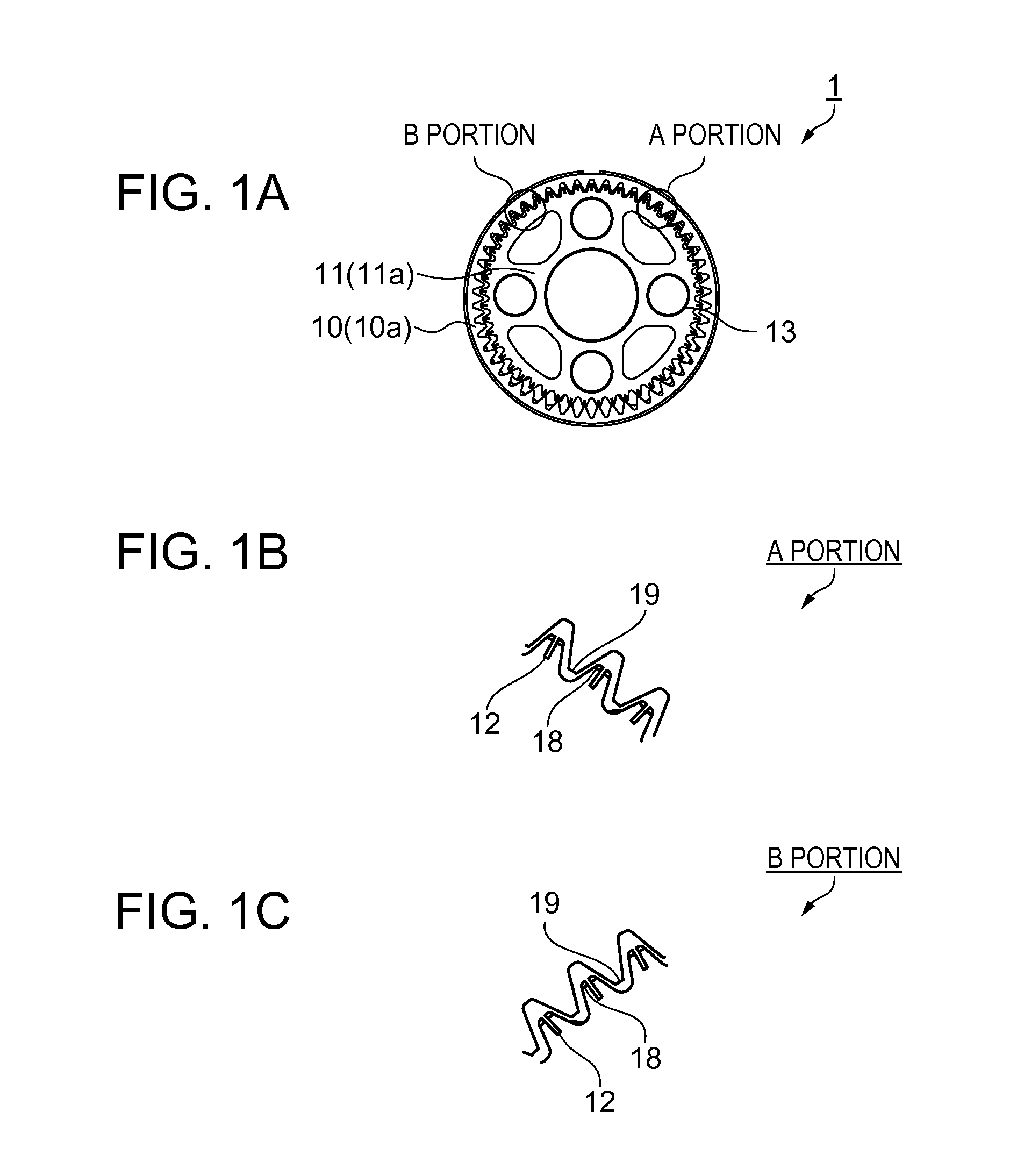
[0029]FIG. 1A is a schematic front view illustrating a structure of a reduction gear according to a first embodiment.

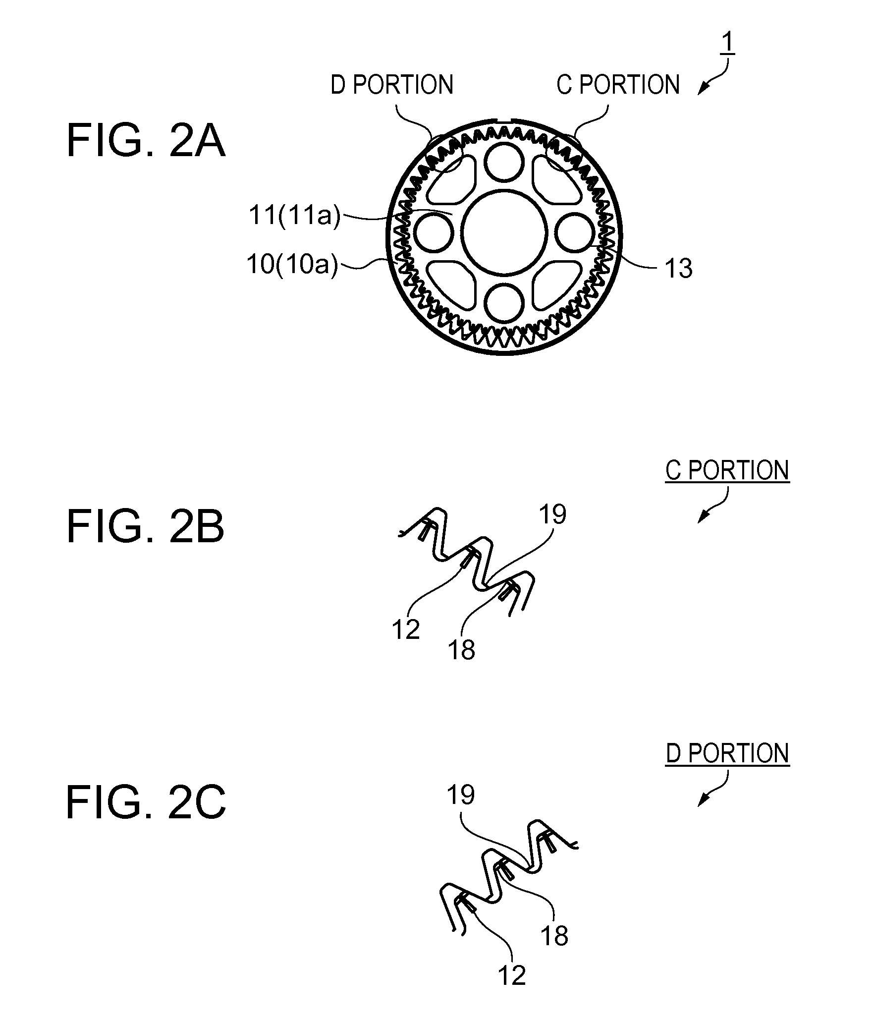
[0030]FIGS. 1B and 1C are enlarged schematic views of the teeth of the reduction gear. FIG. 1B is an enlarged view of A portion in FIG. 1A and FIG. 1C is an enlarged view of B portion in FIG. 1A. FIG. 2A is a schematic front view illustrating a state where the gears are engaged with pressure applied. FIGS. 2B and 2C are enlarged schematic views of the reduction gear teeth in this engaged state. FIG. 2B is an enlarged view of C portion in FIG. 2A and FIG. 2C is an enlarged view of D portion in FIG. 2A. First, a schematic configuration of the reduction gear as a reduction device according to the first embodiment will be described.

[0031]As shown in FIGS. 1A to 1C, a reduction gear 1 of this embodiment includes an inner circumference external tooth gear 11 (an externally toothed inner ring gear) and an outer circumference internal tooth gear 10 (an externally toothed oute...

second embodiment

[0035]FIGS. 3 and 4 are schematic front views illustrating two states of a regulation mechanism for regulating the amount of eccentricity in an eccentric mechanism of the inner circumference external tooth gear according to a second embodiment. FIG. 3 illustrates a state before the regulation mechanism regulates the amount of eccentricity. FIG. 4 illustrates a state after the regulation mechanism regulates the amount of eccentricity. The regulation mechanism will be described with reference to FIGS. 3 and 4. However, no duplicate description of the configurations and portions that are the same as the first embodiment will be provided.

[0036]As shown in FIG. 3, the inner circumference external tooth gear 11 has an eccentric mechanism 17. The eccentric mechanism 17 includes a regulation mechanism 20 for regulating the amount of eccentricity. The outer circumference internal tooth gear 10 has the first teeth 19 arranged along the circumference of a circle and the inner circumference ext...


PUM


Abstract

A reduction gear includes an outer circumference internally toothed gear having first teeth; and an inner circumference externally toothed gear having a second teeth. The reduction gear relatively rotates while the first teeth and the second teeth engage each other. At least one of the first and second teeth has an elastic structure inside the tooth so that the tooth is elastically deformable.

Description

BACKGROUND[0001]1. Technical Field[0002]The present invention relates to a reduction gear.[0003]2. Related Art[0004]JP-A-5-296301 discloses a technique for eliminating reduction gear backlash. In this technique an outer circumference internal tooth gear is formed as a two-stage gear, and the stages are relatively twisted so that backlash between a fixed sun inner circumference gear and a planetary gear, and between a pin and a pin hole, is regulated.[0005]JP-A-4-254045 discloses another technique for eliminating reduction gear backlash. In this technique, as shown in FIGS. 8A and 8B, each gear tooth is formed with a flexible section along one surface which comes into contact with and engages another gear. Accordingly, it is possible to eliminate backlash among the teeth.[0006]However, in the technique for eliminating backlash disclosed in JP-A-5-296301, the ability to regulate the amount of clearance among the teeth is constant and fixed. The clearance is varied by the position of t...

Claims


Application Information

Patent Timeline
IPC IPC(8): F16H1/32F16H55/16
CPCF16H55/18F16H1/32F16H55/16
Inventor KATAOKA, YUYAKINOSHITA, SATOSHIKUSUMOTO, HIROYUKI
Owner SEIKO EPSON CORP
Features
  • Generate Ideas
  • Intellectual Property
  • Life Sciences
  • Materials
  • Tech Scout
  • Unparalleled Data Quality
  • Higher Quality Content
  • 60% Fewer Hallucinations
Learn More