Heel Counter Structure for a Shoe

a technology for counter structures and shoes, applied in the direction of uppers, bootlegs, stiffners, etc., can solve the problems of shortening the life of shoes, unstable support of the heel, and sore

Active Publication Date: 2012-12-06
MIZUNO CORPORATION
View PDF11 Cites 45 Cited by
  • Summary
  • Abstract
  • Description
  • Claims
  • Application Information

AI Technical Summary

Benefits of technology

[0010]A heel counter structure for a shoe according to the present invention includes a sole plate that is provided at least at a heel region of the shoe and that has a peripheral portion upraised along the heel region of the shoe so as to enclose a lower portion of a heel portion of a foot of a shoe wearer, and a pair of heel counter portions provided on

Problems solved by technology

However, in the structure shown in the above-mentioned publication, since an upraised portion whose upper end edge portion extends to the vicinity of the ridge line of the widest region of the foot is adapted to hold an entire heel, in the event that a width of the sole of the shoe corresponds to a heel width of the foot of a wearer, it can hold the heel sufficiently, but in the event that the heel width of the foot is smaller than the width of the sole of the shoe, a gap is created between the heel and the shoe and thus it cannot hold the heel sufficiently thereby causing support of the heel to be unstable.
Thereby, the structure cannot hold th

Method used


Image

  • Heel Counter Structure for a Shoe
  • Heel Counter Structure for a Shoe
  • Heel Counter Structure for a Shoe

Examples


first embodiment

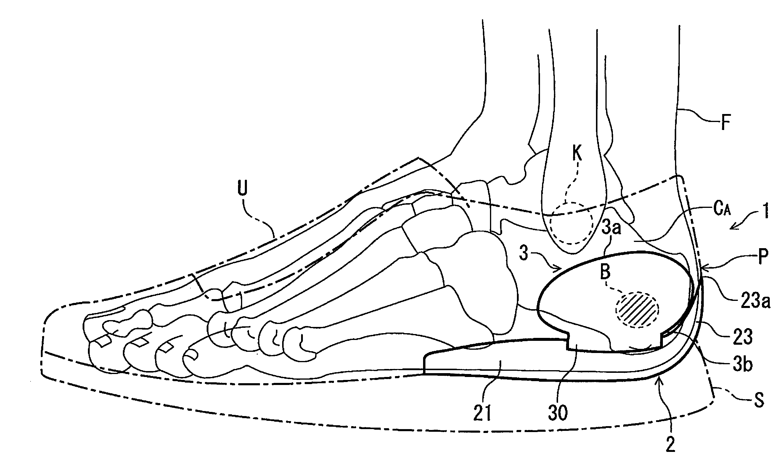
[0063]Referring now to the drawings, FIGS. 1 to 8 show a heel counter structure for a shoe according to a first embodiment of the present invention. In these drawings, like reference numbers indicate identical or functionally similar elements. In the exemplification, the heel counter structure is applied to a walking shoe or a running shoe. Of course, it also has an application to shoes of different kinds.

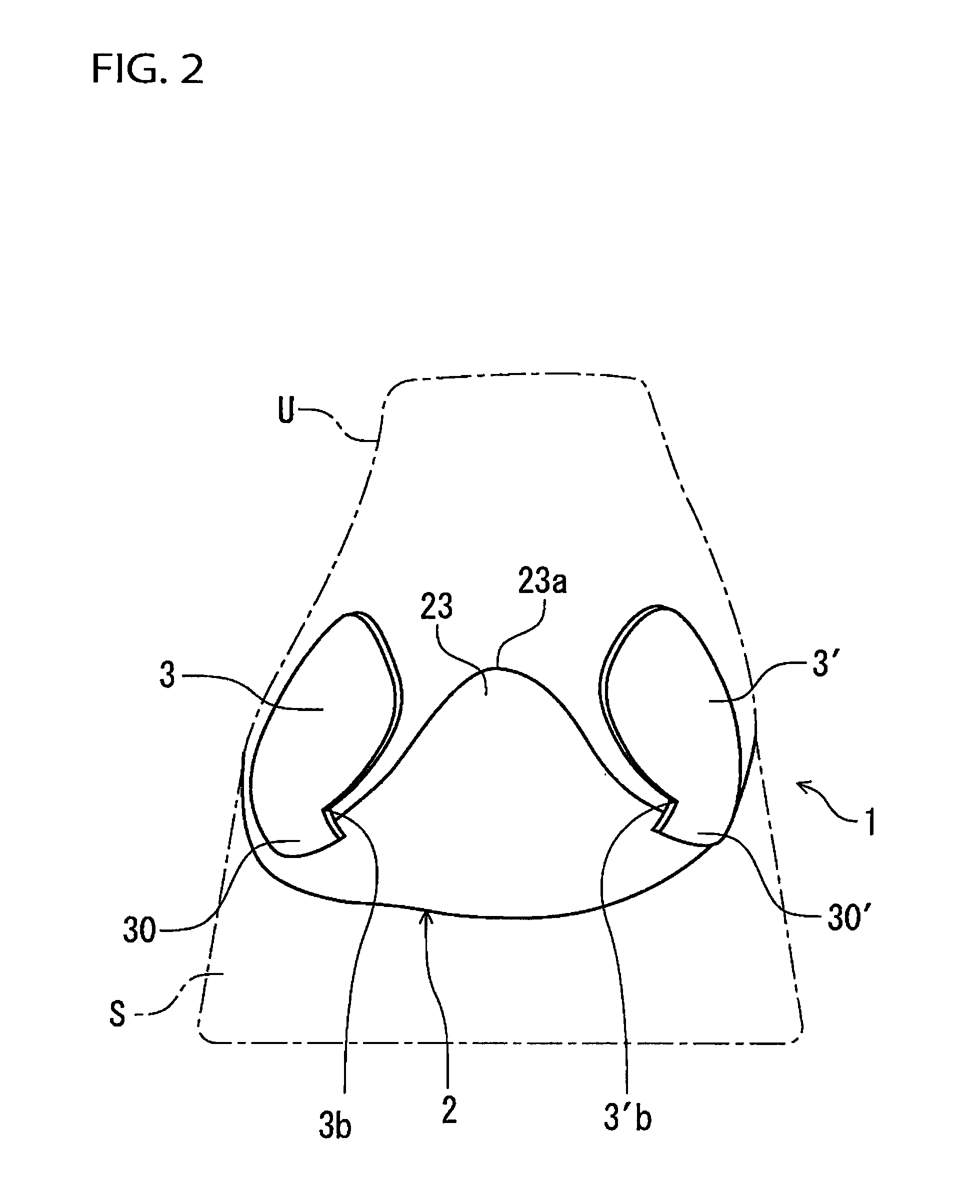
[0064]As shown in FIGS. 1 and 2, a shoe includes a sole S and an upper U provided on and fixedly attached to the sole S to cover a foot F of a shoe wearer. A heel counter structure 1 includes a sole plate 2 provided at least at a heel region of the shoe and a pair of heel counter members 3, 3′ provided at and extending upwardly from the sole plate 2.

[0065]The sole plate 2 in this example extends from a heel rear end to the vicinity of a midfoot region of the shoe. Also, as shown in FIGS. 5 to 8, the sole plate 2 has an insole board 20 and peripheral portions 21, 22, 23 provided alo...

second embodiment

[0085]In the above-mentioned first embodiment, the connecting portions 30, 30′ of the heel counter members 3, 3′ were disposed outside the peripheral portions 21, 22 of the sole plate 2, but application of the present invention is not restricted to such an example.

[0086]FIGS. 9 to 13 show a heel counter structure according to a second embodiment of the present invention. In these drawings, like reference numbers indicate identical or functionally similar elements. This second embodiment differs from the first embodiment in that the connecting portion 30, 30′ of the heel counter members 3, 3′ were disposed inside the peripheral portions 21, 22 of the sole plate 2.

[0087]In the second embodiment as well, when wearing the shoe, the heel lower portion of the foot of the wearer is held by the peripheral portions 21, 22, 23 of the sole plate 2 and the heel portion of the foot is sandwiched by the heel counter members 3, 3′ sideways attached to the peripheral portions 21, 22 of the sole pla...

third embodiment

[0091]In the above-mentioned first and second embodiments, the lower ends of the heel counter members 3, 3′ were disposed outside or inside the peripheral portions 21, 22 of the sole plate 2, but application of the present invention is not restricted to these examples.

[0092]FIGS. 14 to 18 show a heel counter structure according to a third embodiment of the present invention. In these drawings, like reference numbers indicate identical or functionally similar elements. The third embodiment is different from the first and second embodiments in that lower end surfaces of the heel counter members 3, 3′ were positioned against and connected to upper end surfaces of the peripheral portions 21, 22 of the sole plate 2. That is, in this third embodiment, the heel counter members 3, 3′ are fixedly attached (e.g. glued or sewed) directly to the upper end surfaces of the peripheral portions 21, 22 of the sole plate 2 through connecting portions 31, 31′ provided at bottom portions of the heel co...


PUM

PropertyMeasurementUnit
Shapeaaaaaaaaaa
Heightaaaaaaaaaa

Abstract

The heel counter structure includes a sole plate provided at least at the heel region of the shoe and having a peripheral portion. The peripheral portion is upraised along the heel region of the shoe so as to enclose the lower portion of the heel portion of the foot of the wearer. The heel structure also includes a pair of heel counter portions provided on the medial and lateral sides of the heel region of the shoe so as to sandwich the heel portion of the foot sideways. The heel counter portions are coupled to the peripheral portion of the sole plate at the lower ends of the heel counter portions so that the heel counter portions can tilt inwardly and outwardly independently of the sole plate. The heel counter portions are separated from the peripheral portion of the sole plate except the lower ends of the heel counter portions.

Description

BACKGROUND OF THE INVENTION[0001]The present invention relates generally to a heel counter structure for a shoe, and more particularly, to improvement in structure to hold a heel of a foot of a shoe wearer stably at all times irrespective of width of the heel or size of calcaneus of the foot.[0002]The applicant of the present invent ion proposed a sole structure for an athletic sports shoe in which a sole has a three-dimensional upraised shape to enclose a region extending from a ball of a foot in front of a plantar arch portion to a heel portion and an upper end edge portion of the upraised shape extends to a vicinity of a ridge line of the widest region of the foot (see figured 1 and 3 of Japanese utility model registration application examined publication No. H07-36481 or 1995-36481).[0003]In this case, giving a three-dimensional shape to the sole allows for secure support of the heel without a heel counter for holding the heel.[0004]However, in the structure shown in the above-m...

Claims


Application Information

Patent Timeline
IPC IPC(8): A43B23/08
CPCA43B23/027A43B23/088A43B23/087A43B7/144A43B7/20
Inventor KIMURA, TAKAYADAZAI, TATSUYAODA, TAKAO
Owner MIZUNO CORPORATION
Why Eureka
Try Eureka