Heel counter structure for a shoe
a technology for counter structures and shoes, applied in the direction of uppers, bootlegs, stiffners, etc., can solve the problems of shortening the life of shoes, unstable support of the heel, and sore
- Summary
- Abstract
- Description
- Claims
- Application Information
AI Technical Summary
Benefits of technology
Problems solved by technology
Method used
Image
Examples
first embodiment
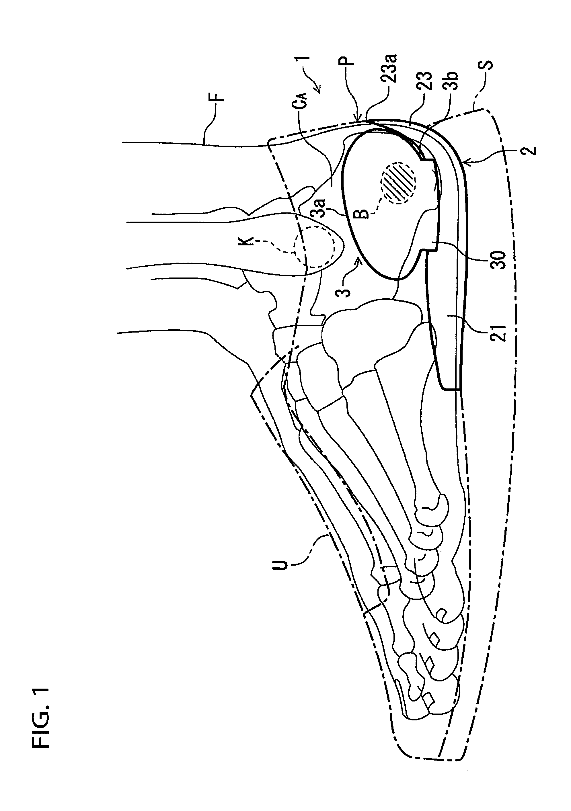
[0063]Referring now to the drawings, FIGS. 1 to 8 show a heel counter structure for a shoe according to a first embodiment of the present invention. In these drawings, like reference numbers indicate identical or functionally similar elements. In the exemplification, the heel counter structure is applied to a walking shoe or a running shoe. Of course, it also has an application to shoes of different kinds.
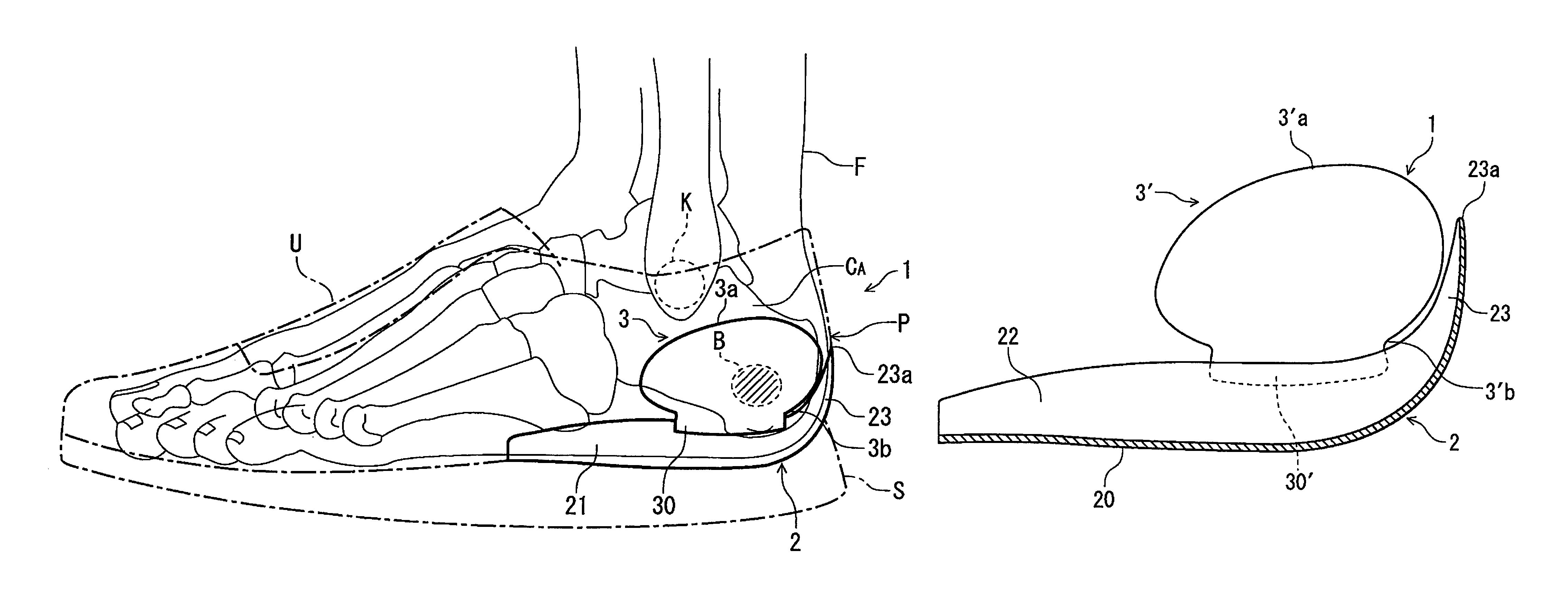
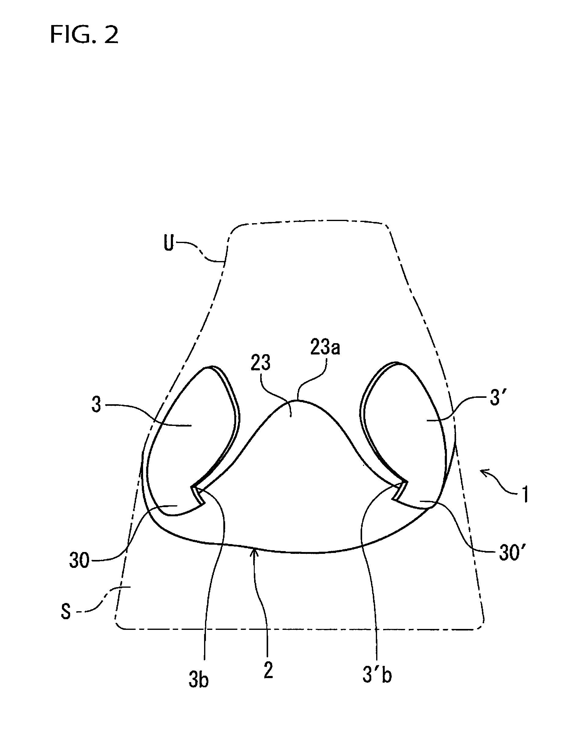
[0064]As shown in FIGS. 1 and 2, a shoe includes a sole S and an upper U provided on and fixedly attached to the sole S to cover a foot F of a shoe wearer. A heel counter structure 1 includes a sole plate 2 provided at least at a heel region of the shoe and a pair of heel counter members 3, 3′ provided at and extending upwardly from the sole plate 2.
[0065]The sole plate 2 in this example extends from a heel rear end to the vicinity of a midfoot region of the shoe. Also, as shown in FIGS. 5 to 8, the sole plate 2 has an insole board 20 and peripheral portions 21, 22, 23 provided alo...
second embodiment
[0085]In the above-mentioned first embodiment, the connecting portions 30, 30′ of the heel counter members 3, 3′ were disposed outside the peripheral portions 21, 22 of the sole plate 2, but application of the present invention is not restricted to such an example.
[0086]FIGS. 9 to 13 show a heel counter structure according to a second embodiment of the present invention. In these drawings, like reference numbers indicate identical or functionally similar elements. This second embodiment differs from the first embodiment in that the connecting portion 30, 30′ of the heel counter members 3, 3′ were disposed inside the peripheral portions 21, 22 of the sole plate 2.
[0087]In the second embodiment as well, when wearing the shoe, the heel lower portion of the foot of the wearer is held by the peripheral portions 21, 22, 23 of the sole plate 2 and the heel portion of the foot is sandwiched by the heel counter members 3, 3′ sideways attached to the peripheral portions 21, 22 of the sole pla...
third embodiment
[0091]In the above-mentioned first and second embodiments, the lower ends of the heel counter members 3, 3′ were disposed outside or inside the peripheral portions 21, 22 of the sole plate 2, but application of the present invention is not restricted to these examples.
[0092]FIGS. 14 to 18 show a heel counter structure according to a third embodiment of the present invention. In these drawings, like reference numbers indicate identical or functionally similar elements. The third embodiment is different from the first and second embodiments in that lower end surfaces of the heel counter members 3, 3′ were positioned against and connected to upper end surfaces of the peripheral portions 21, 22 of the sole plate 2. That is, in this third embodiment, the heel counter members 3, 3′ are fixedly attached (e.g. glued or sewed) directly to the upper end surfaces of the peripheral portions 21, 22 of the sole plate 2 through connecting portions 31, 31′ provided at bottom portions of the heel co...
PUM
| Property | Measurement | Unit |
|---|---|---|
| shape | aaaaa | aaaaa |
| height | aaaaa | aaaaa |
| longitudinal length | aaaaa | aaaaa |
Abstract
Description
Claims
Application Information
 - R&D
- Intellectual Property
- Life Sciences
- Materials
- Tech Scout
- Unparalleled Data Quality
- Higher Quality Content
- 60% Fewer Hallucinations
Browse by: Latest US Patents, China's latest patents, Technical Efficacy Thesaurus, Application Domain, Technology Topic, Popular Technical Reports.
© 2025 PatSnap. All rights reserved.Legal|Privacy policy|Modern Slavery Act Transparency Statement|Sitemap|About US| Contact US: help@patsnap.com


