Busbar unit and motor

a busbar unit and motor technology, applied in the field of busbar units, can solve the problems of inefficiency in connecting the terminal to the coil terminal, the orientation of the coil terminal needs to be adjusted, and the material yield of the busbar is not very high, so as to improve the workability of attaching the busbar. the effect of improving the material yield of the busbar

Active Publication Date: 2012-12-20
NIDEC CORP
View PDF4 Cites 48 Cited by
  • Summary
  • Abstract
  • Description
  • Claims
  • Application Information

AI Technical Summary

Benefits of technology

[0009]According to the busbar unit described above, the busbars and the terminal members preferably are defined separately from one another, and each of the busbars is preferably defined by a wire. Therefore, an improvement in the material yield of the busbars is achieved. In addition, each of the terminal members includes the coil connection portion arranged to be connected with one of the coil wire terminals arranged to extend in the axial direction of the stator. This makes it possible to connect the busbars with the corresponding coil wire terminals without the need for an operation of adjusting the orientation of any coil wire terminal.
[0010]The busbar unit according to a preferred embodiment of the present invention is able to achieve an improvement in the material yield of the busbars, and also an improvement in workability in attaching the busbars.

Problems solved by technology

Therefore, the material yield of the busbars is not very high.
However, the motor described in JP-A 2004-56873 has a disadvantage in that the orientation of the coil terminals needs to be adjusted when the terminals are connected to the coil terminals.
Therefore, according to the motor described in JP-A 2004-56873, an operation of connecting the terminals to the coil terminals cannot be performed efficiently.

Method used


Image

  • Busbar unit and motor
  • Busbar unit and motor
  • Busbar unit and motor

Examples


Embodiment Construction

[0069]Hereinafter, preferred embodiments of the present invention will be described in detail with reference to the accompanying drawings. Note that the following description is meant to be merely illustrative, and should not be construed to restrict the scope of the present invention, applications thereof, or purposes thereof.

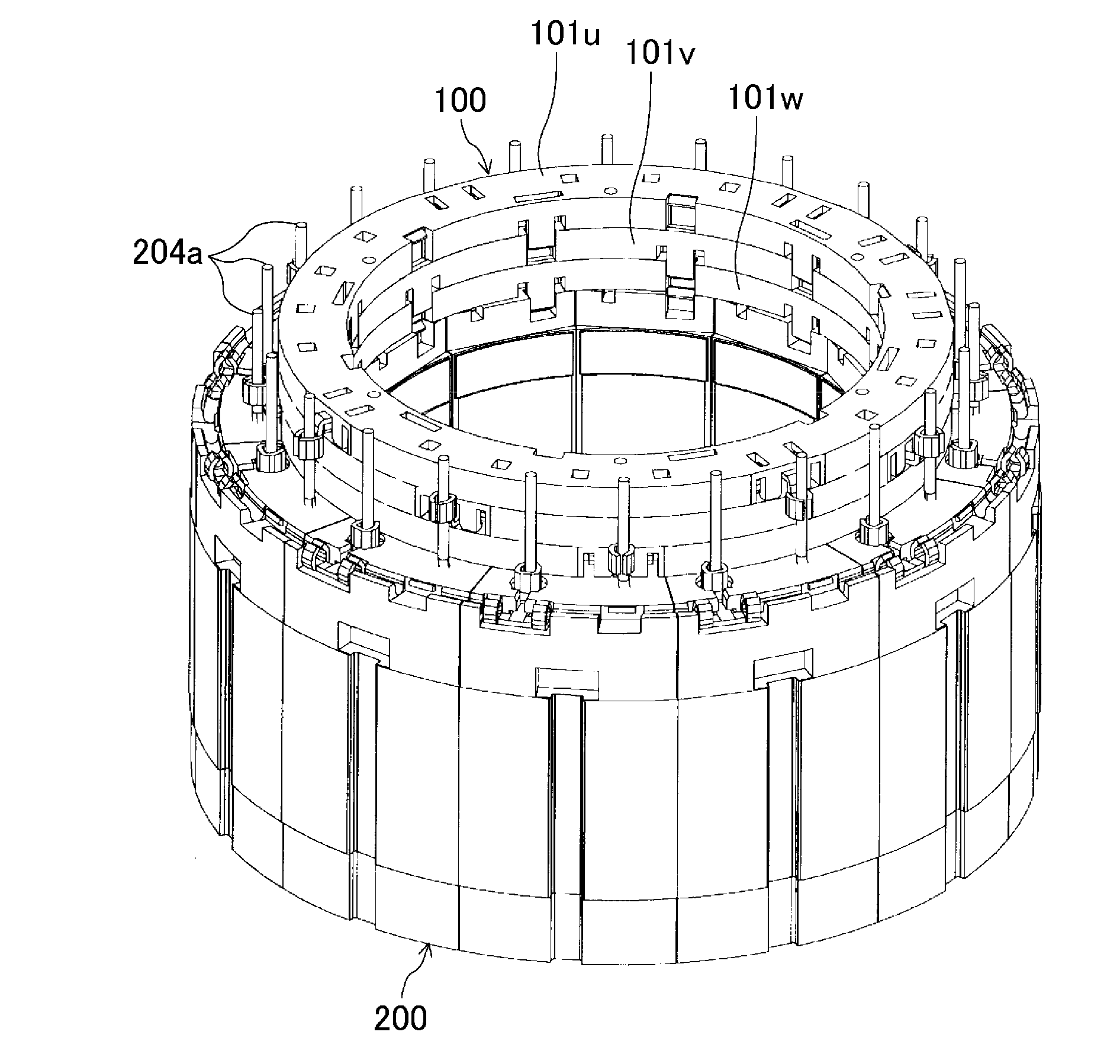
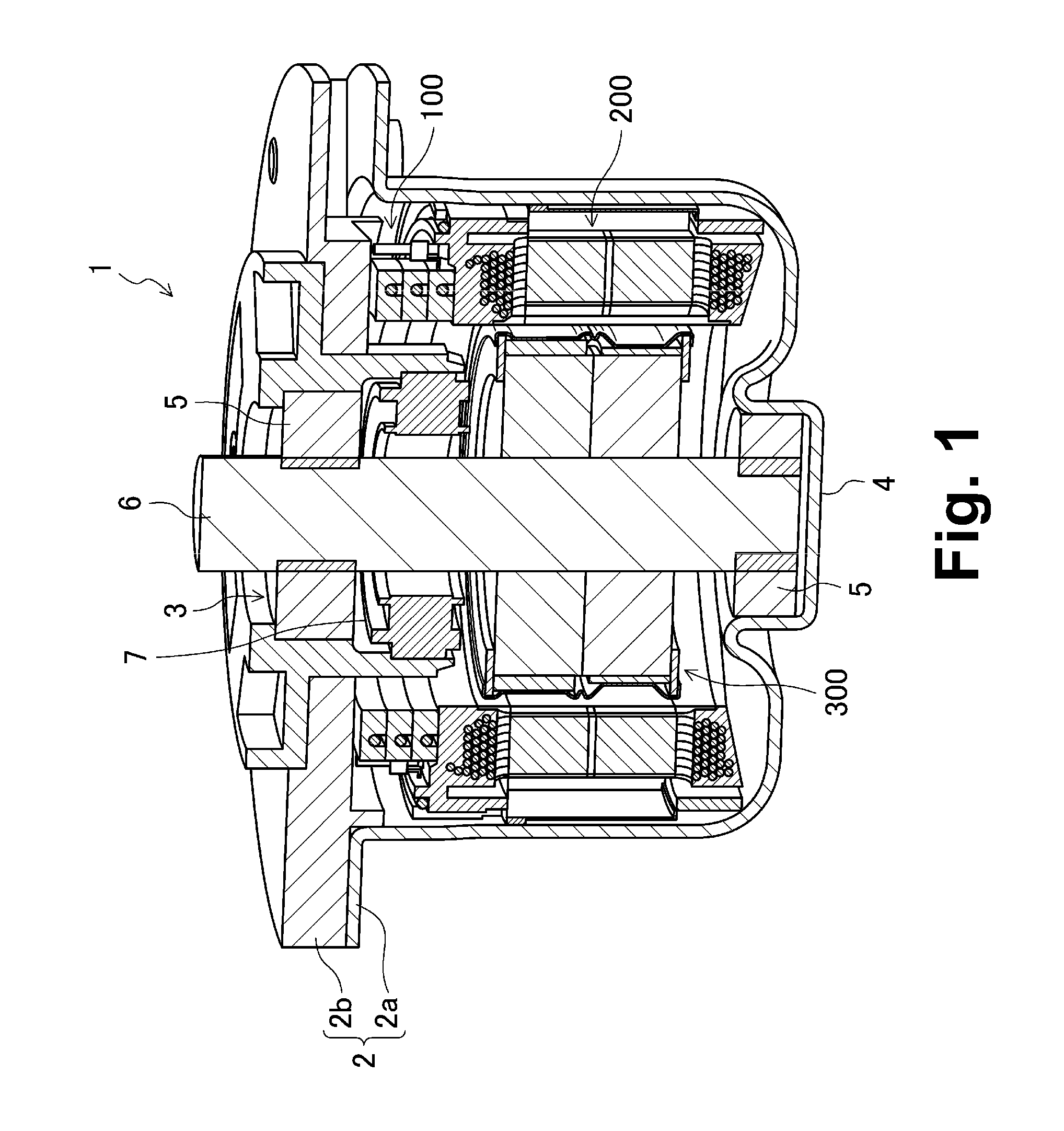
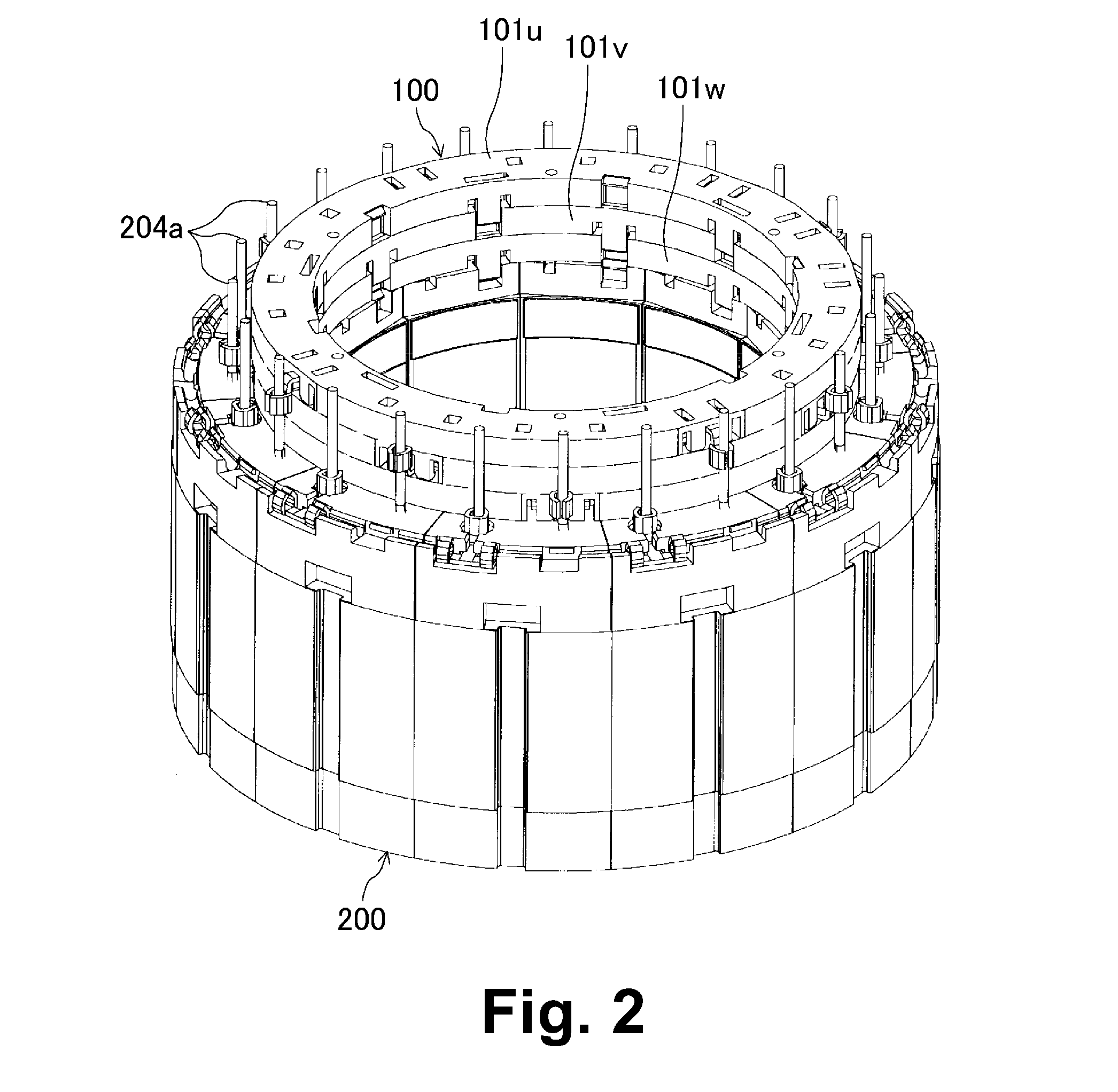
[0070]FIG. 1 illustrates a motor 1 including a rotor 300 according to a preferred embodiment of the present invention. The motor 1 is preferably an inner-rotor brushless motor to be installed in a vehicle, for example, and is preferably used to drive an electric power steering, for example. As illustrated in FIG. 1, the motor 1 preferably includes a casing 2, a busbar unit 100, a stator 200, the rotor 300, a shaft 6, and so on.

[0071]The casing 2 preferably includes a receptacle 2a which has a bottom and is substantially cylindrical, and a substantially disc-shaped lid 2b. The lid 2b is secured to a flange of the receptacle 2a. The flange of the receptacle 2a i...


PUM


Abstract

A busbar unit is arranged on an axial end portion of a stator and electrically connected with a plurality of coil wire terminals arranged to project in an axial direction above the axial end portion of the stator. The busbar unit includes a plurality of busbars each including a body portion defined by an electrically conductive wire having an annular or “C” shape, the body portion being arranged around an axis of the stator; a holder member arranged on the axial end portion of the stator to hold the busbars; and a plurality of terminal members each including a busbar connection portion connected with the body portion of one of the busbars, and a coil connection portion connected with one of the coil wire terminals.

Description

BACKGROUND OF THE INVENTION[0001]1. Field of the Invention[0002]The present invention relates to a busbar unit, and more specifically, to an inner-rotor motor including a busbar unit.[0003]2. Description of the Related Art[0004]FIGS. 4 and 5 of JP-A 2000-333400 show a busbar which is connected with coil terminals from a stator and arranged to supply currents to coils. A plurality of such busbars (lead frames) are placed one upon another, and each of the busbars (lead frames) is defined by a plate material having a substantially annular shape in plan view. Each busbar (lead frame) and a plurality of terminals are defined integrally with each other. The terminals are arranged to project in a radial direction from an outer circumference or an inner circumference of each busbar. In short, each busbar (lead frame) is defined by a substantially annular plate material having a plurality of terminals projecting therefrom in the radial direction. Therefore, the material yield of the busbars ...

Claims


Application Information

Patent Timeline
Patent Type & Authority Applications(United States)
IPC IPC(8): H02K3/28
CPCH02K1/148H02K1/278H02K3/522H02K5/225H02K2203/12H02K15/095H02K15/12H02K2203/09H02K15/03
Inventor NAKAGAWA, AIRI
Owner NIDEC CORP
Why Eureka
Try Eureka