METHOD OF PRODUCING Ni-BASED SUPERALLOY

a superalloy and ni-based technology, applied in forging/pressing/hammering machines, manufacturing tools, forging/pressing/hammering apparatus, etc., can solve the problems of cracks, hot working, and become much more difficult to strictly control the grain size in production, so as to improve the yield of materials and increase the operation temperature. , the effect of high strength

Active Publication Date: 2018-03-01
HITACHI METALS LTD
View PDF0 Cites 6 Cited by
  • Summary
  • Abstract
  • Description
  • Claims
  • Application Information

AI Technical Summary

Benefits of technology

[0020]According to the present invention, in a Ni-based superalloy which is used in an aircraft engine, a gas turbine for power generation, or the like and has high strength, since crack in the surface of the produced hot working material by the decrease of the temperature does not occur, yield of the material is improved in comparison to that in a producing method of the related art. In addition, it is possible to obtain a hot working material having a homogeneous microstructure in which coarsening or incipient melting of crystal grains by working heat generation does not occur. Since strength is higher than that of an alloy used in the related art, an operation temperature can be increased and contribution to high efficiency is expected by using the material in the above-described heat engine.

Problems solved by technology

However, as the size of materials of a product is increased, it becomes much more difficult to strictly control the grain size.
However, if the amount of Al, Ti, Nb, or Ta which is a constituent element of such a γ′ phase is increased, the amount of the γ′ phase which is a strengthening phase becomes excessive, and thus, it is difficult to perform hot working represented by press forging and the excessive amount of the γ′ phase causes a crack to occur in a hot working material in production.
Thus, a component such as Al or Ti, which contributes to strengthening is generally limited in comparison to a cast alloy which is obtained without hot working.
Thus, hot working is very difficult.
At this time, a problem remains in that the γ′ phase is precipitated in the process of cooling the surface of the material, and the precipitated γ′ phase causes deformation resistance to be increased and causes a hot working crack in the surface.
Thus, hot workability of the hot working material is significantly degraded and a crack often occurs in the hot working material by the working.
In the latter case, there are problems in that the amount of hot working for one time is necessarily small and energy required for production is increased, and that, since non-uniform deformation by hot working plural number of times easily occurs, it is difficult to obtain a desired product shape, and that homogeneity of the microstructure is easily lost.

Method used


Image

  • METHOD OF PRODUCING Ni-BASED SUPERALLOY
  • METHOD OF PRODUCING Ni-BASED SUPERALLOY
  • METHOD OF PRODUCING Ni-BASED SUPERALLOY

Examples


example 1

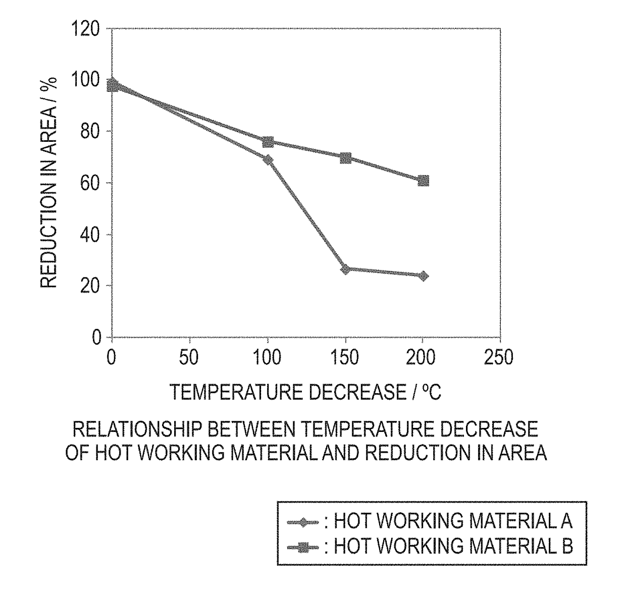
[0067]In order to confirm the effect of the present invention by using a hot working material for a large-size Ni-based superalloy, two hot working materials A and B were prepared. The hot working material A is a Ni-based superalloy corresponding to Udimet720Li. The hot working material B is a Ni-based superalloy corresponding to one disclosed in Patent Document 1. The hot working materials A and B are alloys having a chemical composition on which performing hot working is most difficult from a viewpoint of the amount of the γ′ phase, among superalloys for hot forging. For each material, hot forging and mechanical working were performed on a columnar Ni-based superalloy ingot which had been produced by using a vacuum arc remelting method which is an industrial melting method. The hot working materials A and B are formed to have a shape of φ203.2 mm×400 mmL as dimensions. Chemical composition of the hot working materials A and B are shown in Table 1.

TABLE 1(mass %)MaterialCAlTiNbTaCr...

example 2

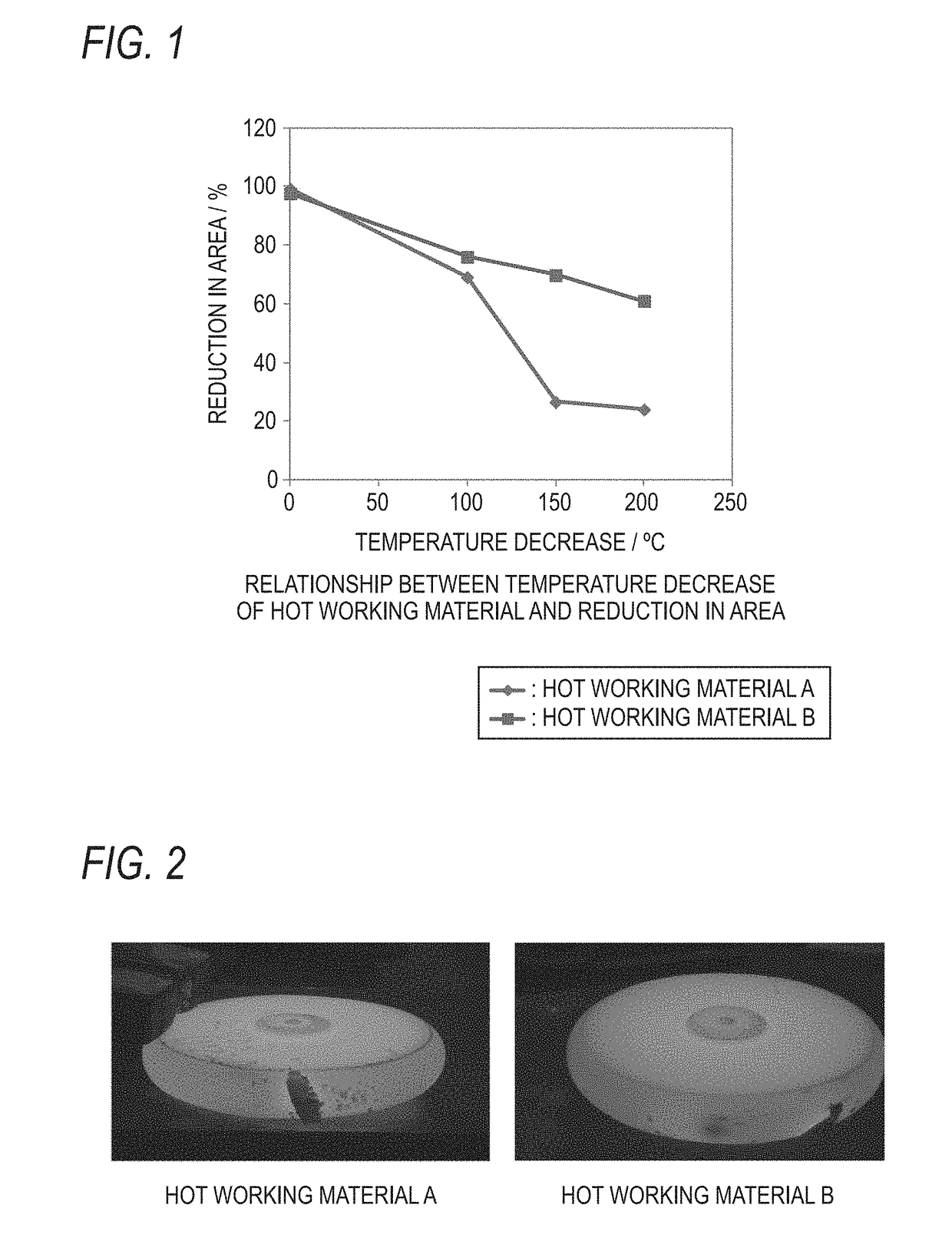
[0071]In order to confirm the effect of the present invention, a forming work in which a disk material which had dimensions equivalent to those of the practical product and has a pancake shape was produced was performed on the hot working materials A and B. The materials were heated to 1100° C. in an atmospheric furnace, and then pressure of 80% was applied under a condition of a strain rate of 0.01 / second in a free forging press machine in which the temperature of a die was set to 900° C. Thereby, a pancake-like disk having an outer diameter of about 470 mm and a height of 80 mm was formed. The following Table 3 shows the heating temperature in a forging process and a disk surface temperature when forging is ended.

TABLE 3Heating temperatureMaterial surfaceMaterialDimensions(° C.) of hot workingtemperature (° C.) whendimensions(mm) afterMaterialmaterialforging is ended(mm)forgingA11001009φ203.2 × 400φ477 × 80.5B11001002φ203.2 × 400φ477 × 80.0

[0072]According to Table 3, it is implied...


PUM

PropertyMeasurementUnit
temperatureaaaaaaaaaa

Abstract

A method of producing a Ni-based super heat-resistant alloy in which a hot working material is subjected to hot working with a mold is provided. The hot working material consists of, in mass %, 0.001 to 0.050% of C, 1.0% to 4.0% of Al, 3.0% to 7.0% of Ti, 12% to 18% of Cr, 12% to 30% of Co, 1.5% to 5.5% of Mo, 0.5% to 2.5% of W, 0.001% to 0.050% of B, 0.001% to 0.100% of Zr, 0% to 0.01% of Mg, 0% to 5% of Fe, 0% to 3% of Ta, 0% to 3% of Nb, and the remainder of Ni and impurities. The method includes: heating and holding the hot working material in a temperature range of 950° C. to 1150° C. for 1 hour or longer; and performing hot working on the material with the mold that is heated to a temperature range of 800° C. to 1150° C.

Description

TECHNICAL FIELD[0001]The present invention relates to a method of producing a Ni-based superalloy.BACKGROUND ART[0002]A Ni-based superalloy which includes many alloy elements such as Al and Ti and is a γ′ (gamma prime) phase-precipitation strengthened type is used as a heat resistant member for aircraft engines and gas turbines for power generation.[0003]A Ni-based forged alloy has been used as a turbine disk which requires high strength and reliability among components of a turbine. Here, the forged alloy is a term used in contrast to a cast alloy having a cast solidification structure which is used itself. The forged alloy is a material produced through a process in which an ingot obtained by melting and solidification is subjected to hot working and thereby a predetermined component shaped is made. Since hot working causes a cast solidification structure which is coarse and heterogeneous to be changed to a forged structure which is fine and homogeneous, mechanical characteristics...

Claims


Application Information

Patent Timeline
Patent Type & Authority Applications(United States)
IPC IPC(8): C22F1/10C22C19/05B21J1/06
CPCC22F1/10C22C19/056B21J1/06B21J5/00B21J13/02C22C19/051C22C19/05C22F1/00
Inventor KOBAYASHI, SHINICHIUENO, TOMONORIOHNO, TAKEHIRO
Owner HITACHI METALS LTD
Why Eureka
Try Eureka