Device and method for the evaporative deposition of a coating material

a coating material and device technology, applied in the direction of ion implantation coating, chemical vapor deposition coating, coatings, etc., can solve the problems of difficult to evaporate mixtures of materials, the film composition on a large area is inevitable, and the coating technology is very demanding

Active Publication Date: 2006-03-09
THEVA DUENNSCHICHTTECHN
View PDF6 Cites 6 Cited by
  • Summary
  • Abstract
  • Description
  • Claims
  • Application Information

AI Technical Summary

Benefits of technology

[0015] With the device according to the invention, equilibrium is reached within the evaporation zone between the continuous evaporation of material by the energy transferring medium and the continuous material supply by the conveyor. Since the evaporation essentially without residues at a constant rate (adjustable by the material supply) occurs essentially in equilibrium and from an essentially stationary point source, a sophisticated rate control is not necessary and the composition of the deposited film is more homogenous across the entire deposition area than with already known deposition techniques. Further, in the device according to the invention the substrate can be placed very close to the evaporation zone and can cover a large angle in space to increase the evaporation material yield. This is a big advantage over arrangements with several sources (co-evaporation, MBE), which have to keep a certain minimum distance to limit deviations of the composition.
[0017] In a first preferred embodiment the evaporation device comprises an electron beam evaporator which can be preferably modulated. However, also arrangements for generating other high energy particle beams (e.g. ion beam bombardment) or using Lasers are possible. At present, electron beams are preferred because they are comparatively cheap and can be easily modulated.
[0023] Further the device contains preferably means that enable a gas supply close to the substrate, as described in DE 19 680 845 C1. Thereby it is possible to compensate for the loss of gaseous components of the evaporation material during evaporation.

Problems solved by technology

Since many compounds only exhibit the desired properties if the film is of high crystalline perfection, the requirements on the coating technology are very demanding.
Furthermore, since the material components do not originate from a single point source and react sensitively on local physical deposition parameters like substrate temperature or gas pressure, deviations of the film composition on a large area are inevitable.
However, it is problematic to evaporate mixtures of material where the individual components are strongly differing in vapor pressure, or compounds that are chemically destroyed upon electron beam irradiation (cracking) or fractionate.
However, the results achieved therewith are poor.
This problem can be faced by a rapid deflection of the electron beam into several, independent crucibles and the respective dwell times. However, this again means accepting the disadvantages of multiple, locally separated sources, i.e. gradients in the composition across larger areas.
The problem of this arrangement, however, is that the capacity of the crucibles is limited and a continuous refilling is ruled out due to the rotation.
The method is therefore not appropriate for continuous long—term coating, which requires a large volume of material.
For static evaporator crucibles such refilling devices are known e.g. from JP 61 003 880 A. Evaporation from a static crucible or gradual evaporation even from a crucible in motion leads to fractioning of complex compounds, like e.g. oxidic high temperature superconductors, and to problems with the chemical composition of the coating.
The results of these experiments, however, were not satisfactory.
Since the initial powder material exhibits a large internal surface and is partially hygroscopic, the grains absorb a lot of water.
Upon strong heating the water evaporates instantaneously leading to explosions of the powder grains, which hurl them out of the evaporation zone instead of transferring them into the gas phase.
Because of the above explained processing route of Davis et al. for flash evaporation it is immediately clear that this method is not appropriate for larger quantities of material or for continuous operation.
Furthermore, it turned out that the droplets with a mass of around 0.1 g were already too big to be transferred into the gas phase instantaneously.
For this reason, the films have to be thermally annealed and even after that exhibit poor quality.

Method used


Image

  • Device and method for the evaporative deposition of a coating material
  • Device and method for the evaporative deposition of a coating material
  • Device and method for the evaporative deposition of a coating material

Examples


example 1

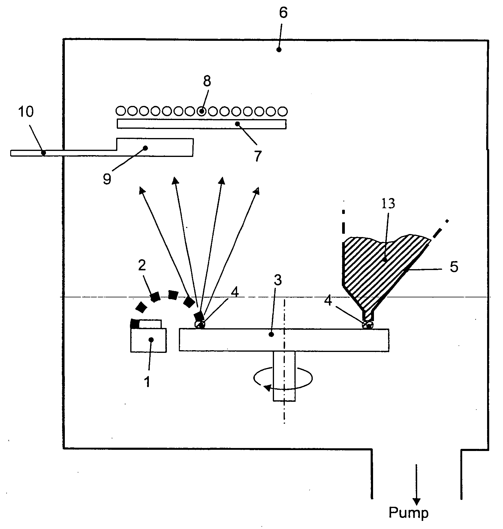
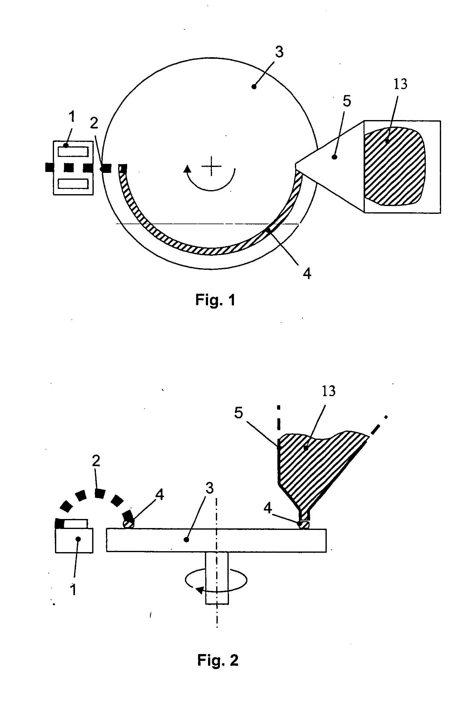
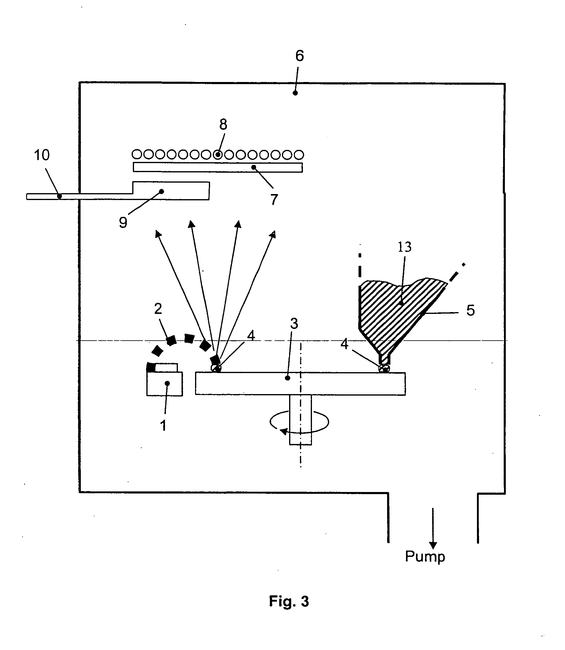
[0055] Granular evaporation material 13 is conducted by a trapezoid funnel 5 onto a rotating, water—cooled copper turntable 3 of an electron beam evaporator 1. Due to the rotation of the turntable 3 a fine trace of material 4 is extracted at the bottom of the funnel 5 and delivered to the electron beam 2 on the opposite side. The power and focus of the electron beam 2 is adjusted in such a way, that upon entering the hot evaporation zone the arriving grains of the evaporation material evaporate rapidly and essentially without residues, i.e. they evaporate quantitatively. The vapor spreads unimpeded within the high vacuum chamber 6 and condenses onto a substrate 7 which can be heated if necessary (cf. Substrate heater 8 in FIG. 3). If required, a reactive gas can also be introduced into the chamber 6 or supplied directly at the substrate 7 by an appropriate device 9, 10.

[0056] In contrast to the mentioned state of the art of Davis et al. the flash evaporation is used as a one-step t...

example 2

[0059] The setup corresponds to that described in example 1. The granulate 13, however, originates from a closed storage container 5 which can be heated by heater elements 11 and which can be pumped at through a pumping neck to remove released residual gas. With such a setup evaporation rates of 5 nm / s have been achieved. For this, a preferred grain size of 100-200 μm has been used and the preferred scanning repetition frequency was 90 Hz. The stoichiometry deviation on an area of 20 cm×20 cm was merely 1%.

example 3

[0060] The setup corresponds to that described in example 1. The granulate 13, however, is supplied through a funnel 5, which is heated only in its bottom outlet section by heater elements 11. The thereby released water vapor is pumped away directly at its origin by a suction pipe 12, preferably with a sieve in front of the inlet (not shown).


PUM

PropertyMeasurementUnit
grain sizeaaaaaaaaaa
repetition frequencyaaaaaaaaaa

Abstract

According to a first aspect, the present invention relates to a device for depositing a high temperature superconductor onto a substrate in vacuum comprising a refilling device for containing a stock of high temperature superconductor material, an evaporation device, that evaporates the high temperature superconductor material within an evaporation zone by means of an energy transferring medium, and a conveyor that transports the high temperature superconductor material continuously from the refilling device to the evaporation zone in such a way that the high temperature superconductor material delivered into the evaporation zone is evaporated essentially without residues. According to a further aspect, the present invention relates to a method to evaporate a high temperature superconductor coating onto a substrate in vacuum, comprising the steps of continuous delivery of granular high temperature superconductor material into an evaporation zone and the operation of a beam of an energy transferring medium, so that the delivered granulate is evaporated in the evaporation zone essentially without residues.

Description

1. TECHNICAL FIELD [0001] The present invention relates to a device and a method for evaporating a coating material in vacuum ambient, particularly for the fabrication of coatings comprising complex inorganic compounds like high temperature superconductors. 2. STATE OF THE ART [0002] Thin films of complex inorganic compounds, e.g. oxides, nitrides, carbides or alloys of various cations, serve as functional coatings or surface hardening in many applications in electronics, optics and mechanical engineering. For example films of PZT (Lead-zirconium-titanate) ceramics or BaTiO3 are used for ferroelectric sensor elements or data memories with high dielectric constant. Thin epitaxial layers of RBa2Cu3O7 (R=yttrium or a rare earth element) become superconducting at low temperatures and can be used e.g. in communication technology for highly selective radio frequency filters, or deposited on flexible metal tapes for conducting electrical current without losses. [0003] For the economic use ...

Claims


Application Information

Patent Timeline
Patent Type & Authority Applications(United States)
IPC IPC(8): C23C16/00C23C14/00C23C14/08C23C14/24C23C14/28C23C14/30
CPCC23C14/0021C23C14/30C23C14/246C23C14/08C23C14/56C23C14/34C23C14/221H01L21/02631
Inventor KINDER, HELMUT
Owner THEVA DUENNSCHICHTTECHN
Why Eureka
Try Eureka