Peripheral viewing system for a vehicle

a peripheral viewing and vehicle technology, applied in the field of vehicle peripheral viewing systems, can solve the problems of frequent replacement of externally mounted side view mirrors, obtrusive external mounting side view mirrors, and blind spots particularly with respect to side view mirrors, so as to enhance vehicle safety and exceed capabilities.

Inactive Publication Date: 2012-12-20
HONG BRIAN KWANGSHIK +1
View PDF5 Cites 8 Cited by
  • Summary
  • Abstract
  • Description
  • Claims
  • Application Information

AI Technical Summary

Benefits of technology

[0010]It is therefore an object of the present invention to provide a vehicle viewing system that greatly exceeds the capabilities of conventional vehicle side and rear view mirrors.
[0011]It is another object of the present invention to provide a viewing system for vehicles that enhances vehicle safety.
[0012]It is yet another object of the present invention to provide a peripheral viewing system for a vehicle that eliminates the problems associated with obtrusive side mounted exterior mirrors.

Problems solved by technology

However, such mirrors have several disadvantages.
The field of view projected by such mirrors is limited thereby resulting in blind spots particularly with respect to the side view mirrors.
The blind spots created by the side view mirrors are responsible for numerous accidents.
In an effort to reduce or eliminate the blind spots, automobile manufacturers employ concave or other reduction type mirrors; though such mirrors are somewhat effective in reducing blind spots, they are deceptive in that objects will appear to be smaller or farther away than actual.
Finally, the externally mounted side view mirrors are obtrusive and often collide with other objects requiring frequent replacement.
The obtrusive mirrors also significantly increase the wind drag on the vehicle.

Method used


Image

  • Peripheral viewing system for a vehicle
  • Peripheral viewing system for a vehicle
  • Peripheral viewing system for a vehicle

Examples


Embodiment Construction

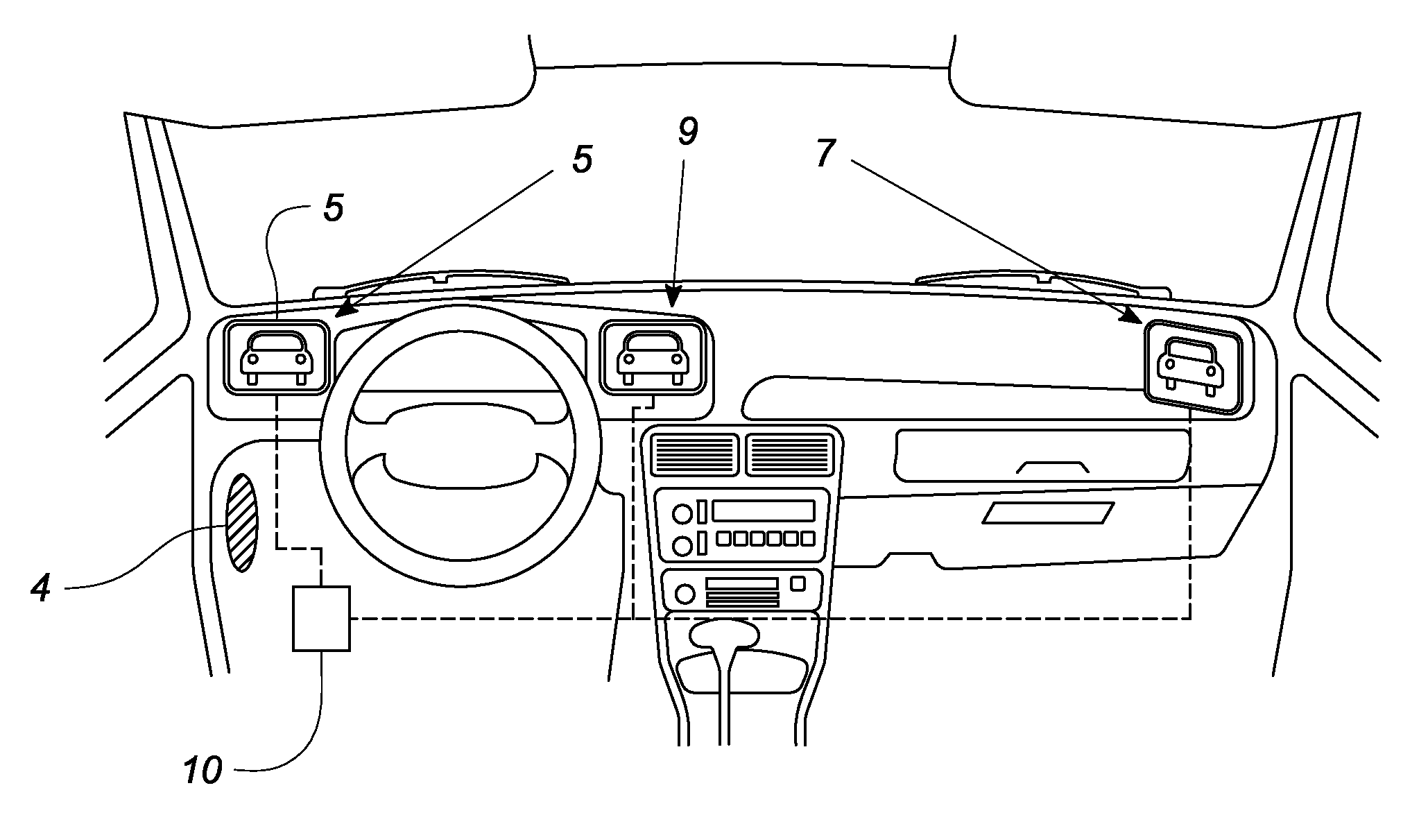
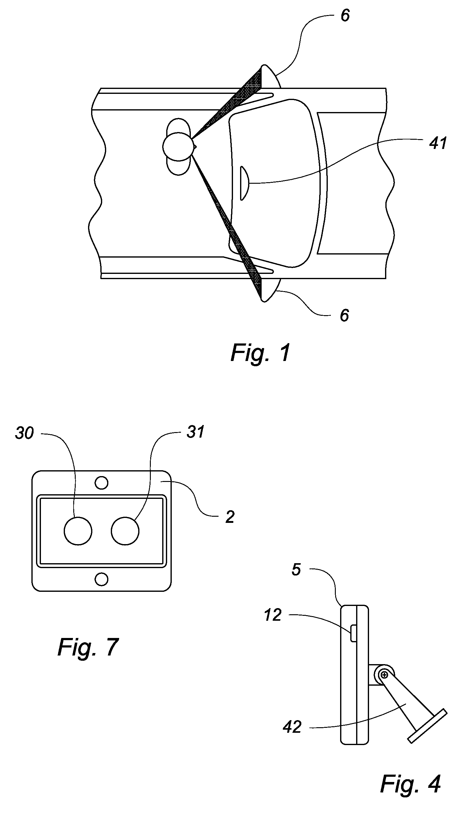
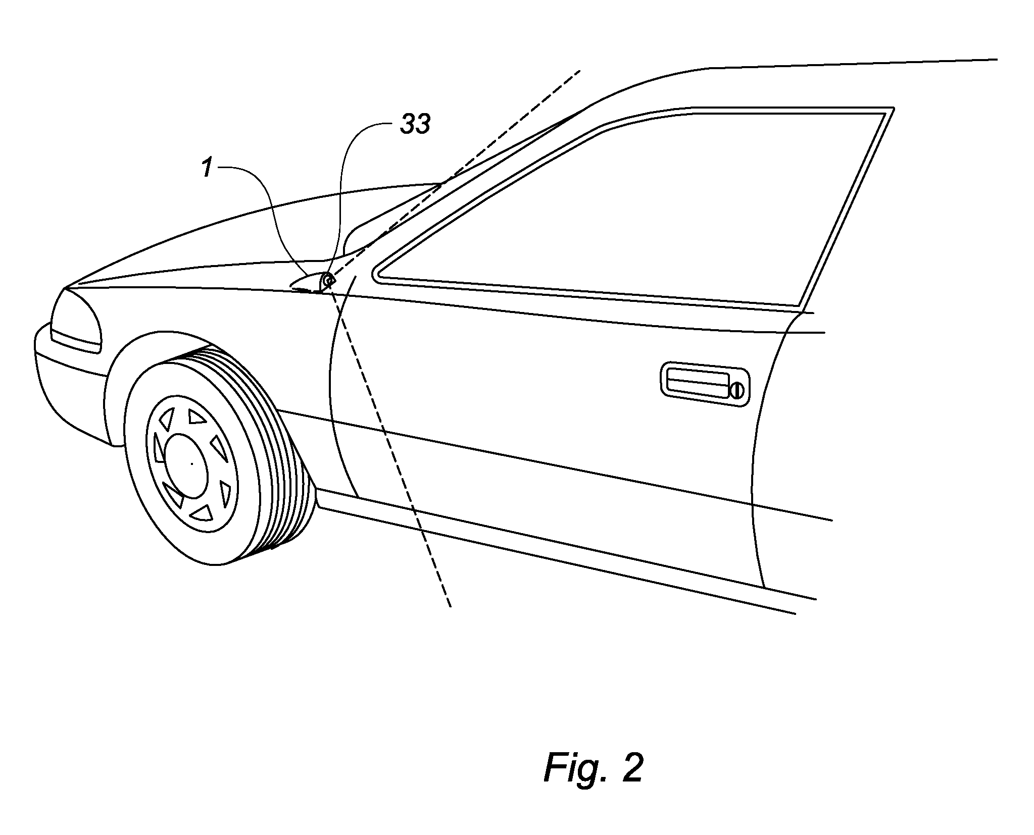
[0021]Now referring to FIGS. 1 through 7, the present invention discloses a peripheral viewing system for a vehicle. The system includes a pair of low profile, externally mounted digital cameras 1 each positioned immediately in front of either the passenger or driver door in generally the same location as a conventional side view mirror 6. Each camera is encased within a contoured, aerodynamic housing 33 to minimize drag. A similar low profile digital camera 3 may be mounted on the vehicle roof immediately adjacent the top edge of the rear window for replacing the conventional rear view mirror 41. Preferably, each camera is a progressive scan, interline-transfer CCD.

[0022]Each camera is electrically connected to a controlling computer 10 mounted within the vehicle passenger compartment. The computer interlinks each camera with a designated liquid crystal display (LCD) or similar video display likewise mounted within the vehicle passenger compartment. Preferably, the display 5 associ...


PUM


Abstract

A peripheral viewing system for a vehicle includes a pair of digital cameras, each positioned on the exterior of the vehicle proximately positioned where a side view mirror would typically be mounted. An additional digital camera is mounted on the vehicle roof immediately adjacent the top edge of the rear window. A plurality of LCD's each discretely associated with a corresponding camera are mounted within the vehicle passenger compartment at a location that is readily observable by the vehicle driver. The driver can panoramically view trailing traffic by observing the LCD's in the passenger compartment. One or more infrared phototransistor receivers are positioned at the rear of the vehicle for detecting oncoming vehicles. If the driver attempts to change lanes and activates a turn signal, a warning message will be emitted within the passenger compartment if any of the transistors detect an approaching vehicle within a predetermined range of the vehicle.

Description

CROSS REFERENCE TO RELATED APPLICATIONS[0001]This application is a continuation application of U.S. application Ser. No. 10 / 675,746, filed on Sept. 30, 2003, which claims the benefit of U.S. Provisional App. No. 60 / 417,986, filed on Oct. 11, 2002. All of the above mentioned applications are incorporated by reference herein in their entireties.BACKGROUND OF THE INVENTION[0002]The present invention relates to an improved peripheral viewing system for a vehicle that replaces conventional side and rearview mirrors.DESCRIPTION OF THE PRIOR ART[0003]Vehicles are typically equipped with externally mounted mirrors on each side, positioned immediately in front of the passenger and driver side doors to allow a driver to determine if vehicles are approaching from an adjacent lane. Vehicles are also equipped with a rearview mirror allowing the driver to observe trailing vehicles. However, such mirrors have several disadvantages. The field of view projected by such mirrors is limited thereby res...

Claims


Application Information

Patent Timeline
Patent Type & Authority Applications(United States)
IPC IPC(8): H04N7/18
CPCH04N7/181G08G1/166B60R11/04H04N5/23238H04N23/698
Inventor HONG, BRIAN KWANGSHIKHONG, RAN SOO
Owner HONG BRIAN KWANGSHIK
Why Eureka
Try Eureka