Storage system for a storage pool and virtual volumes

Active Publication Date: 2012-11-15
HITACHI LTD
View PDF3 Cites 7 Cited by
  • Summary
  • Abstract
  • Description
  • Claims
  • Application Information

AI Technical Summary

Benefits of technology

[0008]According to this invention, the storage areas of virtual volumes accessed by computers can be changed dynamically by changing allocation of logical volumes to the virtual volumes and thus giving the virtual volumes different

Problems solved by technology

In particular, the prior art publication does not disclose how logical volumes are set in virtual volumes an

Method used


Image

  • Storage system for a storage pool and virtual volumes
  • Storage system for a storage pool and virtual volumes
  • Storage system for a storage pool and virtual volumes

Examples


Example

First Embodiment

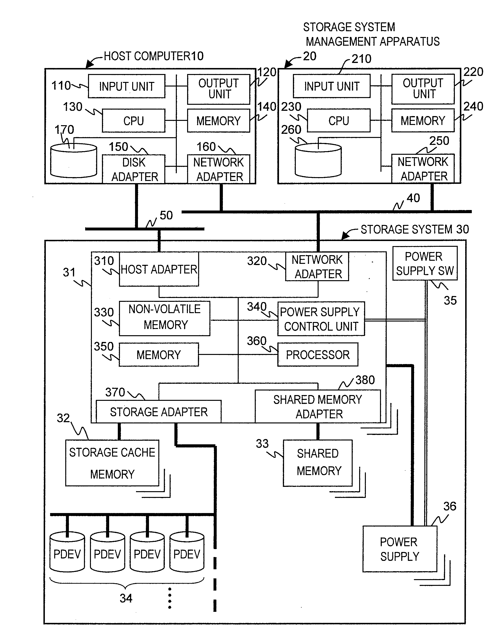
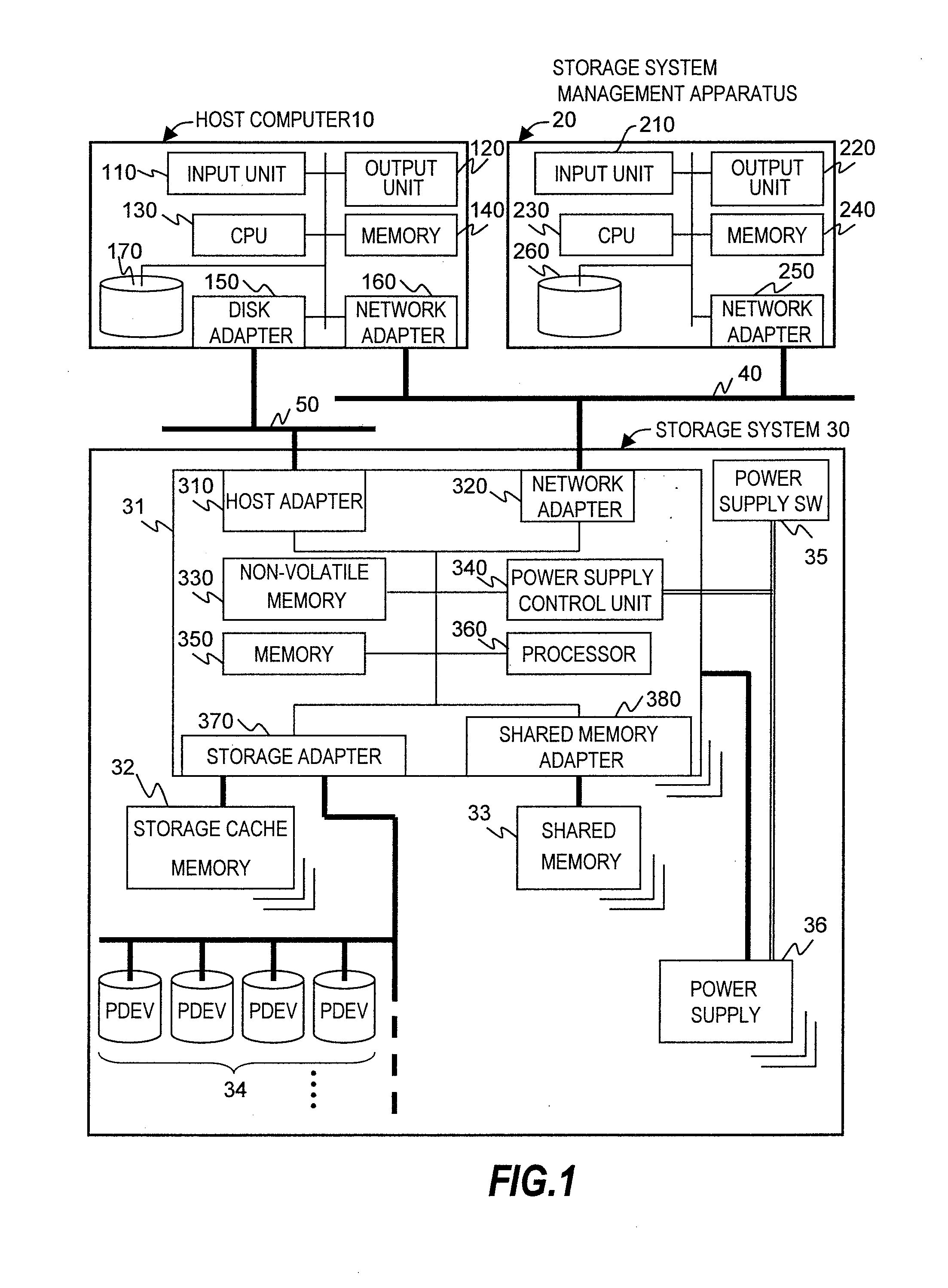
[0042]FIG. 1 is a configuration block diagram of a computer system according to a first embodiment of this invention.

[0043]The computer system of this embodiment has a host computer 10 and a storage system management apparatus 20 which are connected to a storage system 30.

[0044]The host computer 10 accesses data in the storage area of the storage system 30. The storage system management apparatus 20 manages the configuration of the storage area of the storage system 30. The storage system 30 has physical devices 34, 34, 34 . . . , and stores data in storage areas set in the physical devices 34, 34, 34 . . . .

[0045]The host computer 10 has an input unit 110, an output unit 120, a CPU 130, a memory 140, a disk adapter 150, a network adapter 160 and a disk drive 170.

[0046]The input unit 110 accepts an input made by an administrator or the like who operates the host computer 10. The input unit 110 is, for example, a keyboard. The output unit 120 is a unit that displays t...

Example

Second Embodiment

[0396]Now, a computer system according to a second embodiment of this invention is described.

[0397]In this embodiment, the computer system is built as described in the first embodiment and, at the time the power is turned off, the storage system 30 evacuates management information to an area set in a storage pool. This area is called a system area.

[0398]FIG. 27 is an explanatory diagram of a storage pool and the system area according to this embodiment.

[0399]The configuration of the system area is stored in the system area information 3525.

[0400]The system area information 3525 contains a POOL usage amount counter 35251 and an entry 35252.

[0401]The POOL usage amount counter 35231 indicates LDEV information associated with an LDEV of a storage pool. The entry 35252 holds LDEV configuration information of the PVOL 800.

[0402]The entry 35252 contains an LDEV number (LDEV #) 35253, a PVOL address 35254, a POOL-VOL address 35255, a PSCB forward pointer 35256 and a PSCB ba...


PUM


Abstract

This invention provides a storage system to store data used by computers. A storage system coupled to a computer and a management apparatus, includes storage devices accessed by the computer and a control unit that controls the storage devices, in which the control unit performs the following operations: setting, in the storage devices, a first virtual device including a first logical device; setting a second virtual device which including a second logical device, which is a virtual volume accessed by the computer; allocating an address of the first logical device to the second logical device; and changing the allocation to change storage areas of the virtual volume.

Description

CROSS-REFERENCED TO RELATED APPLICATIONS[0001]The present application is a continuation of application Ser. No. 13 / 078,242, filed Apr. 1, 2011; which is a continuation application of application Ser. No. 12 / 915,476, filed Oct. 29, 2010, now U.S. Pat. No. 7,941,630; which is a divisional application of application Ser. No. 11 / 202,033, filed Aug. 12, 2005, now abandoned; which relates to and claims priority from Japanese application P2005-162448 filed on Jun. 2, 2005 and, the contents of which are hereby incorporated by reference into this application.BACKGROUND OF THE INVENTION[0002]This invention relates to a storage system to store data used by computers and, and more specifically to a storage system that allows the capacity of storage accessed by computers to be changed.[0003]The storage capacity of a conventional storage system depends on the capacity of disk drives or other similar physical devices installed in the system. Therefore, when required to have a large storage capacit...

Claims


Application Information

Patent Timeline
IPC IPC(8): G06F12/02
CPCG06F3/0605G06F3/067G06F3/0665G06F3/0631G06F12/08
Inventor EGUCHI, YOSHIAKI
Owner HITACHI LTD
Why Eureka
Try Eureka