Air-blowing system having discharge device

Active Publication Date: 2019-06-27
PANASONIC INTELLECTUAL PROPERTY MANAGEMENT CO LTD
View PDF7 Cites 1 Cited by
  • Summary
  • Abstract
  • Description
  • Claims
  • Application Information

AI Technical Summary

Benefits of technology

[0016]With such a configuration, a fan in the discharge device can be omitted.

Problems solved by technology

Accordingly, the size and cost of the discharge device are increased.
Further, there is also a concern that vibrations and uncomfortable noises occur due to an operation of the fan.
Accordingly, a connection posit

Method used


Image

  • Air-blowing system having discharge device
  • Air-blowing system having discharge device
  • Air-blowing system having discharge device

Examples


Example

First Exemplary Embodiment

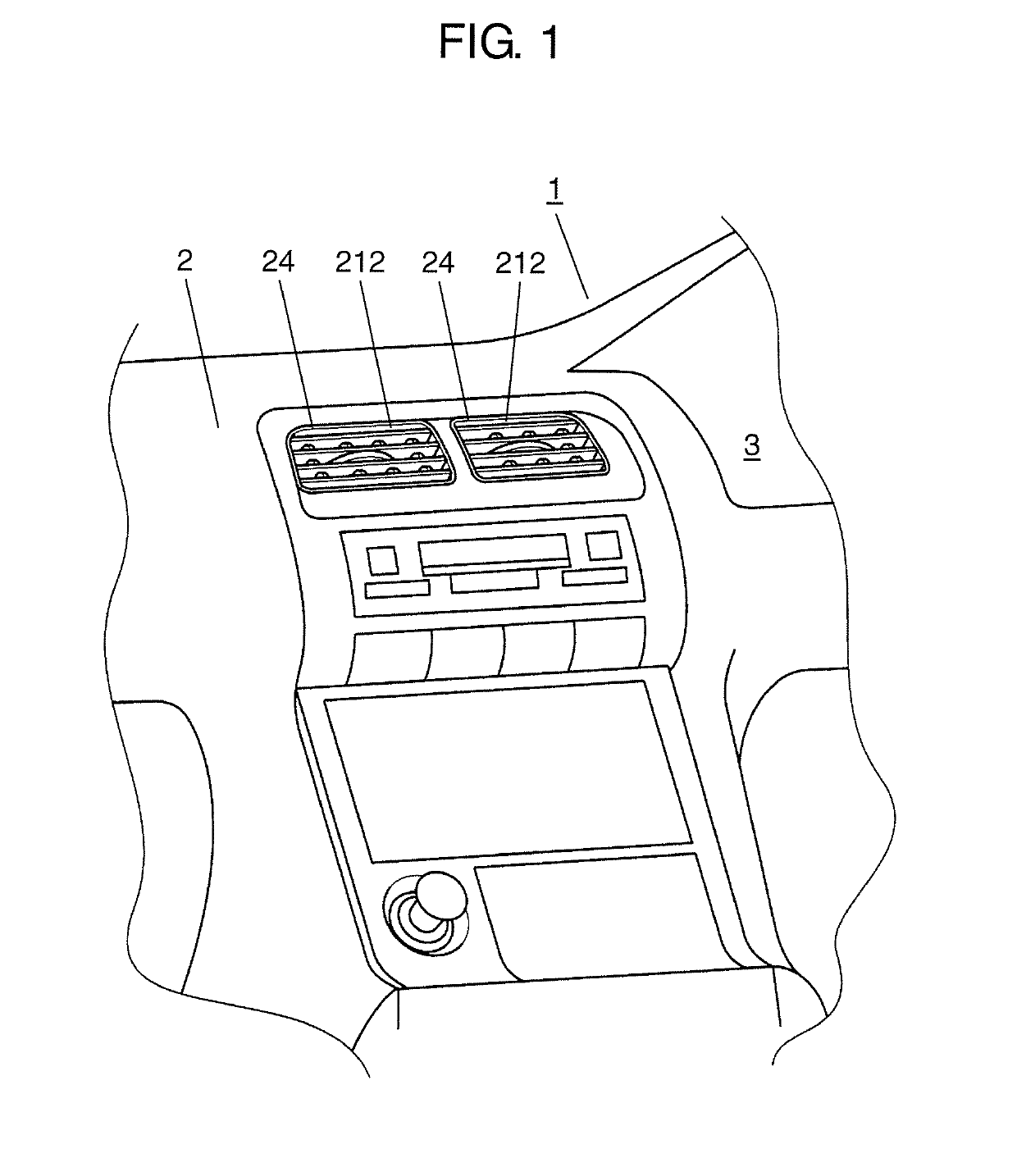
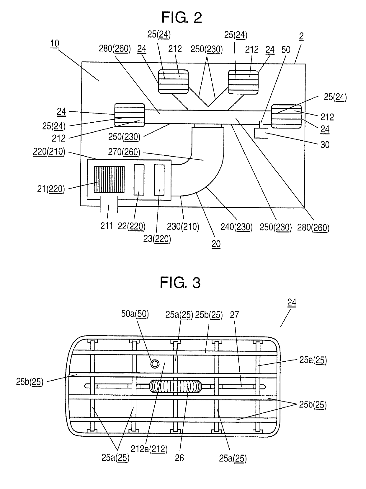
[0029]Hereinafter, the schematic configuration of an air-blowing system having discharge device according to a first exemplary embodiment of the present invention is described with reference to FIG. 1 to FIG. 3.

[0030]Hereinafter, the description is made by taking a device where an electrostatic atomization device is mounted on a vehicle-use air conditioner, which is mounted on vehicle 1, as the air-blowing system having discharge device as an example. The vehicle-use air conditioner is an example of an air-blowing system. The electrostatic atomization device is formed of a discharge portion, a liquid supply portion and the like, and is an example of the discharge device. The electrostatic atomization device generates charged fine water particles of a nanometer size which contain radicals as active ingredients.

[0031]As shown in FIG. 1 and FIG. 2, air conditioner having discharge device 10 according to the present exemplary embodiment includes vehicle-use air...

Example

Second Exemplary Embodiment

[0113]Hereinafter, a configuration of an air-blowing system having discharge device according to a second exemplary embodiment of the present invention, particularly, an arrangement relationship between branch pipe 250 and introducing pipe 50 of electrostatic atomization device 30 is described with reference to FIG. 6.

[0114]FIG. 6 is a view schematically showing a state where the discharge device according to the exemplary embodiment is disposed on the air-blowing system.

[0115]The air-blowing system having discharge device of the present exemplary embodiment uses electrostatic atomization device 30 as the discharge device in the same manner as the above-mentioned first exemplary embodiment. The air-blowing system having discharge device of the present exemplary embodiment is configured to blow off air containing active ingredients generated by electrostatic atomization device 30 into the inside of cabin 3 from air outlet 212 of at least one branch passage ...

Example

Third Exemplary Embodiment

[0129]Hereinafter, a configuration of an air-blowing system having discharge device according to a third exemplary embodiment of the present invention, particularly, an arrangement relationship between branch pipe 250 and introducing pipe 50 of electrostatic atomization device 30 is described with reference to FIG. 7.

[0130]FIG. 7 is a view schematically showing a state where the discharge device according to the exemplary embodiment is disposed on the air-blowing system.

[0131]Here, the air-blowing system having discharge device of the present exemplary embodiment uses electrostatic atomization device 30 as the discharge device in the same manner as the above-mentioned first and second exemplary embodiments. Further, the air-blowing system having discharge device of the present exemplary embodiment is configured to blow off air containing active ingredients generated by electrostatic atomization device 30 into the inside of cabin 3 from air outlet 212 of at ...


PUM


Abstract

An air-blowing system having discharge device includes an air supply passage, and a discharge device provided for generating active ingredients and is disposed outside the air supply passage. Further, the air-blowing system having discharge device includes an introducing pipe having an one end connected to a discharge device and an other end disposed in the air supply passage, and provided for introducing the active ingredients into the air supply passage. The introducing pipe has an opening face on the other end. In the introducing pipe, the opening face and a main stream direction of an air flow, which flows through the air supply passage at a predetermined point of the opening face, are disposed substantially parallel to each other. Thus, an air-blowing system having discharge device with a simplified configuration is provided.

Description

RELATED APPLICATIONS[0001]This application is the U.S. National Phase under 35 U.S.C. § 371 of International Application No. PCT / JP2017 / 030648, filed on Aug. 28, 2017, which in turn claims the benefit of Japanese Application No. 2016-168035, filed Aug. 30, 2016, the disclosures of which are incorporated by reference herein.TECHNICAL FIELD[0002]The present invention relates to an air-blowing system having discharge device.BACKGROUND ART[0003]Conventionally, there has been known an air-blowing system having discharge device which blows off air containing active ingredients to the outside of the air-blowing system (for example, see PTL 1).[0004]The air-blowing system having discharge device described in PTL 1 includes a discharge device mounted on the air-blowing system. The air-blowing system has an air supply passage having an air outlet from which air is blown off. In the air-blowing system, active ingredients generated by the discharge device are introduced into the air supply pass...

Claims


Application Information

Patent Timeline
IPC IPC(8): B60H1/00B60H1/34
CPCB60H1/00564B60H1/34B60H1/00871A61L9/14B05B5/057B60H1/00B60H3/00A61L2209/16A61L2209/134A61L2209/135
Inventor YAMADA, YUSUKESUGAWA, AKIHIDEYANO, TAKESHI
Owner PANASONIC INTELLECTUAL PROPERTY MANAGEMENT CO LTD
Why Eureka
Try Eureka