Optical disk, thin plastic sheet, and method for affixing display sheet to disk substrate

Inactive Publication Date: 2008-04-15
FUJIFILM CORP +1
View PDF14 Cites 3 Cited by
  • Summary
  • Abstract
  • Description
  • Claims
  • Application Information

AI Technical Summary

Benefits of technology

[0012]The invention has been conceived in view of the foregoing circumstances and aims at providing an optical disk capable of preventing warpage of a disk substrate having a cover sheet, and a method for affixing a display sheet to the optical disk, thereby stabilizing read / write characteristics of the optical disk and preventing deterioration of appearance of the optical disk.
[0013]The present inventor has found that machining a plastic sheet into a circular shape and bonding the plastic sheet onto a side of the substrate as a image display layer, the side being opposite to a cover layer on the recording surface side of the substrate, in which the plastic sheet has the same characteristics as those of the cover layer, and thereby a balance between the image display layer and the cover layer can be achieved and that, as a result, a stable characteristic can be obtained even when the disk is preserved at high temperature and high humidity.
[0014]Moreover, the image display layer can be handled in the form of a sheet. After an image has been printed on the image display layer, the layer is affixed to a disk. Alternatively, after the image display layer has been affixed on a disk, an image is printed on the layer. Thus, an image can be printed on a disk by means of any of various techniques, thereby enabling enhancement of a commercial value.

Problems solved by technology

There arises a risk of warpage in a disk substrate 13.
Although a UV laser beam is used for recording operation, application of the UV-ray curing method to curing of a cover layer is less desirable as mentioned above.
There may arise a case where the dimension of a cover layer is changed by thermal shrinkage or moisture shrinkage resulting from the disk being preserved at high temperature and high humidity, thereby imparting “warpage” to the substrate with the cover affixed thereto and inducing a change in the amount of tilt to exert an adverse influence on a recording / reproduction characteristic.

Method used


Image

  • Optical disk, thin plastic sheet, and method for affixing display sheet to disk substrate
  • Optical disk, thin plastic sheet, and method for affixing display sheet to disk substrate
  • Optical disk, thin plastic sheet, and method for affixing display sheet to disk substrate

Examples


first embodiment

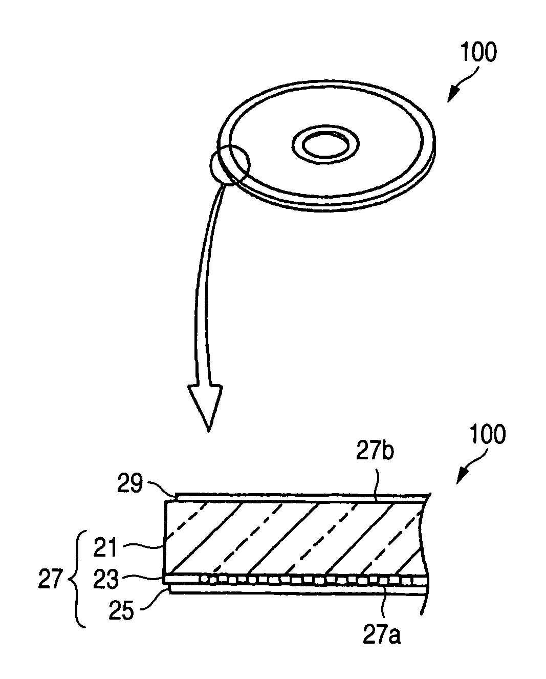
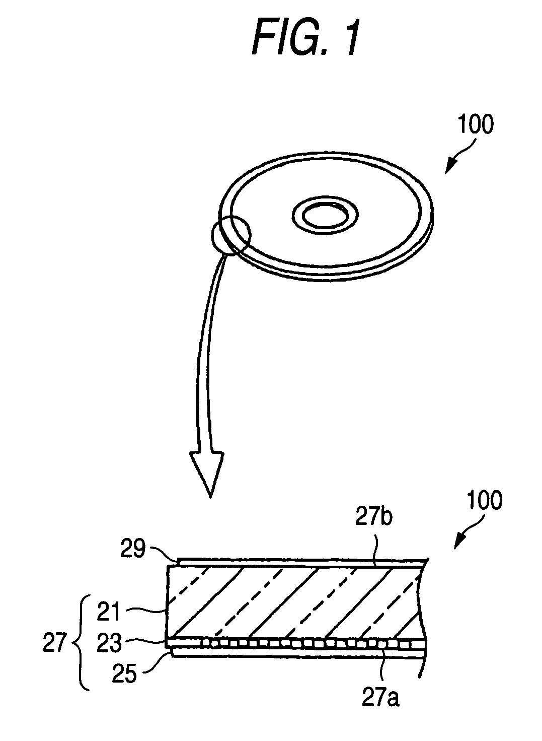
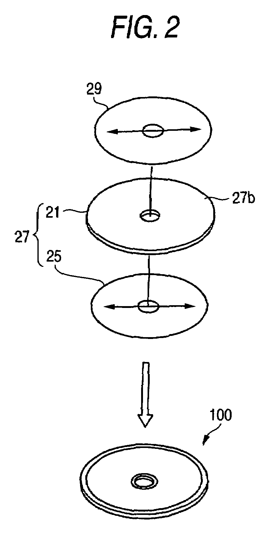
[0070]FIG. 1 is a descriptive view showing the appearance of an optical disk according to the invention and a fragmentary enlarged cross-sectional view of the optical disk. FIG. 2 is a descriptive view showing an exploded perspective view and appearance of the optical disk shown in FIG. 1. FIG. 3 is a descriptive view showing an exploded perspective view and an external perspective view of the disk substrate provided with marks and a display sheet. FIGS. 4A to 4C are descriptive views illustrating kinds of marks. FIG. 5 is a descriptive view representing processes for affixing a display sheet to the substrate.

[0071]In an optical disk 100 according to a first embodiment of the invention, a recording layer 23 is formed on one side of a substrate 21. A cover sheet 25 is integrally provided on the recording layer 23, thus constituting a disk substrate 27. A display sheet 29 is affixed to a surface 27b of the disk substrate 27 opposite to a surface 27a on which the cover sheet 25 is inte...

second embodiment

[0087]FIG. 6 is an exploded perspective view of an optical disk according to the invention.

[0088]In the drawing, reference numeral 39 designates a display sheet; 21 designates a substrate; 25 designates a cover sheet; and 27 designates a disk substrate. A recording layer 23 is formed on a substrate 21, and a cover sheet 25 is integrally provided on the recording layer 23, thus constituting a disk substrate 27. The display sheet 39 is bonded to a surface 27b of the disk substrate 27, the surface 27b being opposite to a surface of the disk substrate 27 on which the cover sheet 25 is integrally provided. The present embodiment is characterized by formation of the display sheet 39 from an image print layer 40 and a fluorescent base layer 41.

[0089]The display sheet 39 is formed from a material having substantially the same physical characteristic as that of the cover sheet 25. Therefore, the display sheet 39 is formed from polycarbonate, TAC, or polyethylene terephthalate.

[0090]The fluor...

third embodiment

[0093]FIG. 7 is an exploded perspective view of an optical disk according to the invention.

[0094]The third embodiment is characterized in that the image print layer 40 of the display sheet 39 is divided into a print section 40a and a non-print section 40b.

[0095]The non-print section 40b may be a section (i.e., a non-print section) which is not actively subjected to printing during printing operation, or a section (i.e., an unprintable section) on which nothing can be printed during printing operation.

[0096]In order to render a section unprintable, the section is coated with a hydrophilic substance.

[0097]As a result, since a solar light beam inevitably passes through the non-print section 40b, and the solar light beam (i.e., UV rays) excites a fluorescent color former of the fluorescent base layer 41 to illuminate, thereby radiating the image print layer 40 from the back thereof. Hence, the image can be seen brightly.

[0098]FIG. 8B shows a longitudinal cross-sectional view of the opt...


PUM


Abstract

An optical disk is provided with a disk substrate having a recording layer formed on one surface of a substrate and a cover sheet applied over the recording layer; and a display sheet which is affixed to a surface of the disk substrate opposite to a surface covered with the cover sheet and which has substantially the same physical characteristic as that of the cover sheet. The display sheet and the cover sheet are substantially brought into coincidence with each other in terms a direction of heat contraction and a heat contraction rate.

Description

BACKGROUND OF THE INVENTION[0001]1. Field of the Invention[0002]The invention relates to an optical disk including a substrate, a recording layer formed on one side of the substrate, and a cover sheet coated over the recording layer, as well as to a method for affixing a display sheet on the optical disk. The invention relates to a disk for recording a large volume of information, and more particularly, to a disk which performs recording operation through use of a UV ray of shorter wavelength, such as a Blu-Ray (blue ray) disk.[0003]2. Description of the Related Art[0004]Development of an optical disk for realizing large-capacity recording has been pursued with a view toward commercialization of an optical disk to be used for performing recording and playback operation through use of a high power violet laser light source. As shown in FIG. 10, a DVD is constructed by laminating together two disk substrates, each having a thickness of 0.6 mm. In contrast, an optical disk 1 adopts a s...

Claims


Application Information

Patent Timeline
IPC IPC(8): G11B7/24G11B7/24053G11B7/24067G11B7/24094G11B7/26G11B23/00G11B23/40
CPCG11B7/24053G11B7/24067G11B7/24094G11B7/26G11B23/0021G11B23/40
Inventor OISHI, KENGO
Owner FUJIFILM CORP
Why Eureka
Try Eureka