Light-emitting device, and electronic device and inspection method using same
Pending Publication Date: 2022-07-28
PANASONIC INTELLECTUAL PROPERTY MANAGEMENT CO LTD
View PDF0 Cites 0 Cited by
Summary
Abstract
Description
Claims
Application Information
AI Technical Summary
This helps you quickly interpret patents by identifying the three key elements:
Problems solved by technology
Method used
Benefits of technology
Benefits of technology
The present invention aims to provide a light emitting device that can use phosphors with both short and long luminescence lifetimes to enhance wavelength selection and afterglow properties of fluorescence. The technical effects include preventing output saturation of fluorescence emitted by the phosphor and improving the efficiency of light emitting. This invention is useful for electronic devices and inspection methods that require longer lifetimes of fluorescence.
Problems solved by technology
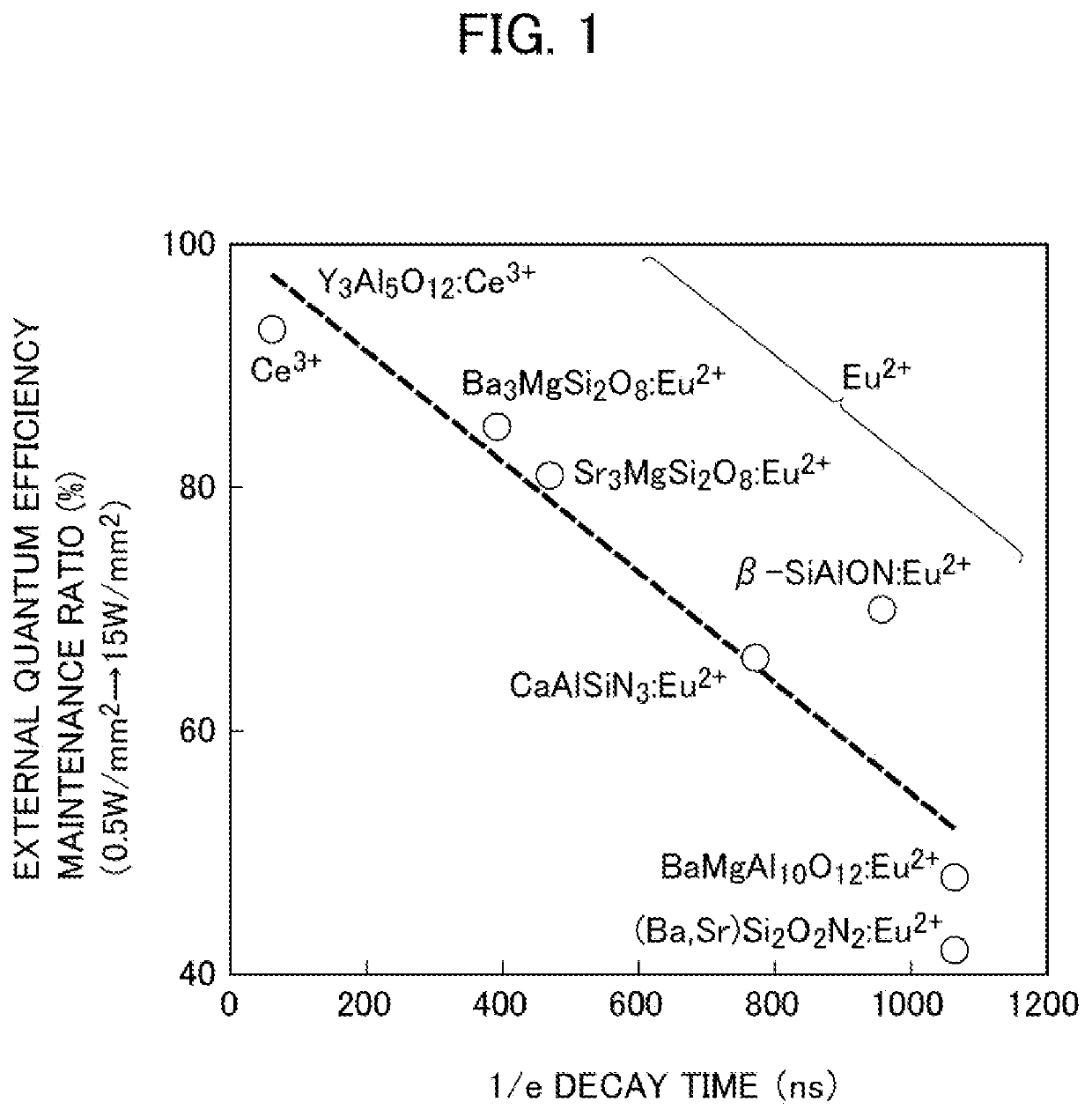
However, when the energy density of the laser beam exceeds a predetermined value, the intensity of the light emitted by the phosphor hardly increases.
Thus, a phosphor having a relatively long luminescence lifetime is considered to be difficult to emit fluorescence with a high intensity as compared with a phosphor having a short luminescence lifetime.
Method used
Image
Click on the blue label to locate the original text in one second.
Reading with bidirectional positioning of images and text.
Examples
example 1
[0141]Next, the light emitting device according to the present embodiment is described in more detail with reference to example 1, but the present embodiment is not limited thereto.
[0142]The oxide phosphor used in example 1-1 was synthesized using a preparation method utilizing a solidphase reaction. The phosphor of example 1-1 is an oxide phosphor represented by a composition formula of (Al0.99, Cr0.01)2O3. The phosphor of example 1-1 is a Cr3+-activated phosphor.
[0143]In synthesizing the oxide phosphor of example 1-1, the following compound powders were used as main raw materials.
[0144]Aluminum hydroxide oxide (AlOOH): purity 2N5, manufactured by KAWAI LIME INDUSTRY CO., LTD.
[0146]First, the above-described raw materials were weighed to obtain a compound of a stoichiometric composition (Al0.99, Cr0.01)2O3. The weighed raw materials were then put into a beaker containing pure water and stirred with a magnetic stirrer for 1 hour. Thus, a slurry-like mixed raw material of the pure water and raw materials was obtained. Then, the slurry-like mixed raw material was dried...
example 1-2
[0148]The oxide phosphor used in example 1-2 was synthesized using a preparation method utilizing a solidphase reaction. The phosphor of example 1-2 is an oxide phosphor represented by a composition formula of Gd3(Ga0.97, Cr0.03)5O12. The phosphor of example 1-2 is a Cr3+-activated phosphor.
[0149]In synthesizing the oxide phosphor of example 1-2, the following compound powders were used as main raw materials.
[0150]Gadolinium oxide (Gd2O3): purity 3N, Wako Pure Chemical Corporation
[0151]Gallium oxide (Ga2O3): purity 4N, Wako Pure Chemical Corporation
[0153]First, the above-described raw materials were weighed to obtain a compound of a stoichiometric composition Gd3(Ga0.97, Cr0.03)5O12. The weighed raw materials were then put into a beaker containing pure water and stirred with a magnetic stirrer for 1 hour. Thus, a slurry-like mixed raw material of the pure water and raw materials was obtained. Then, the sl...
PUM
Abstract
A light emitting device includes a light source that emits a primary light having a light energy density exceeding 0.5W / mm2, and a first phosphor that absorbs the primary light to convert the primary light into a first wavelength-converted light having a wavelength longer than that of the primary light. The first phosphor includes a compound serving as a host, the compound being a simple oxide including one kind of metal element or a composite oxide including a plurality of different kinds of the simple oxide as an end member. When an energy conversion value at a peak wavelength of the primary light is E1 electron volts and an energy conversion value at a fluorescence peak wavelength of the first wavelength-converted light is E2 electron volts, a bandgap energy of a crystal of the simple oxide is larger than a sum of the E1 electron volts and the E2 electron volts.
Description
TECHNICAL FIELD[0001]The present invention relates to a light emitting device, and an electronic device and an inspection method using the light emitting device.BACKGROUND ART[0002]There has been known a light emitting device including a combination of an excitation light source for emitting a laser beam and a wavelength converter including multiple kinds of phosphors. As a light emitting device having such a light source for emitting a laser beam, for example, a laser lighting device or a laser projector is known. The light emitting device having a light source for emitting a laser beam generally performs high light density excitation of phosphors.[0003]In such a light emitting device, the intensity (luminance) of light emitted by a phosphor tends to increase as the energy density of a laser beam from an excitation light source increases. However, when the energy density of the laser beam exceeds a predetermined value, the intensity of the light emitted by the phosphor hardly incre...
Claims
Application Information
Patent Timeline
Application Date:The date an application was filed.
Publication Date:The date a patent or application was officially published.
First Publication Date:The earliest publication date of a patent with the same application number.
Issue Date:Publication date of the patent grant document.
PCT Entry Date:The Entry date of PCT National Phase.
Estimated Expiry Date:The statutory expiry date of a patent right according to the Patent Law, and it is the longest term of protection that the patent right can achieve without the termination of the patent right due to other reasons(Term extension factor has been taken into account ).
Invalid Date:Actual expiry date is based on effective date or publication date of legal transaction data of invalid patent.

