
Connector

Active Publication Date: 2020-05-14
SUMITOMO WIRING SYST LTD
View PDF0 Cites 1 Cited by
  • Summary
  • Abstract
  • Description
  • Claims
  • Application Information

AI Technical Summary

Benefits of technology

The patent ensures the male connector is watertight and can be operated even if the female connector is small. The female connector may have its own lock to keep it secure. This allows for more flexibility in the design of the female receptacle.

Problems solved by technology

Further, the projection interferes with a sealing member that is mounted in the receptacle and can damage the sealing member in the process of connecting the connectors.
A damaged sealing member cannot ensure proper sealing.
For example, if the receptacle is provided with a structure, such as the plate lock, it is difficult to provide a pedestal to hold the sealing member in the receptacle.

Method used


Image

  • Connector
  • Connector
  • Connector

Examples


Embodiment Construction

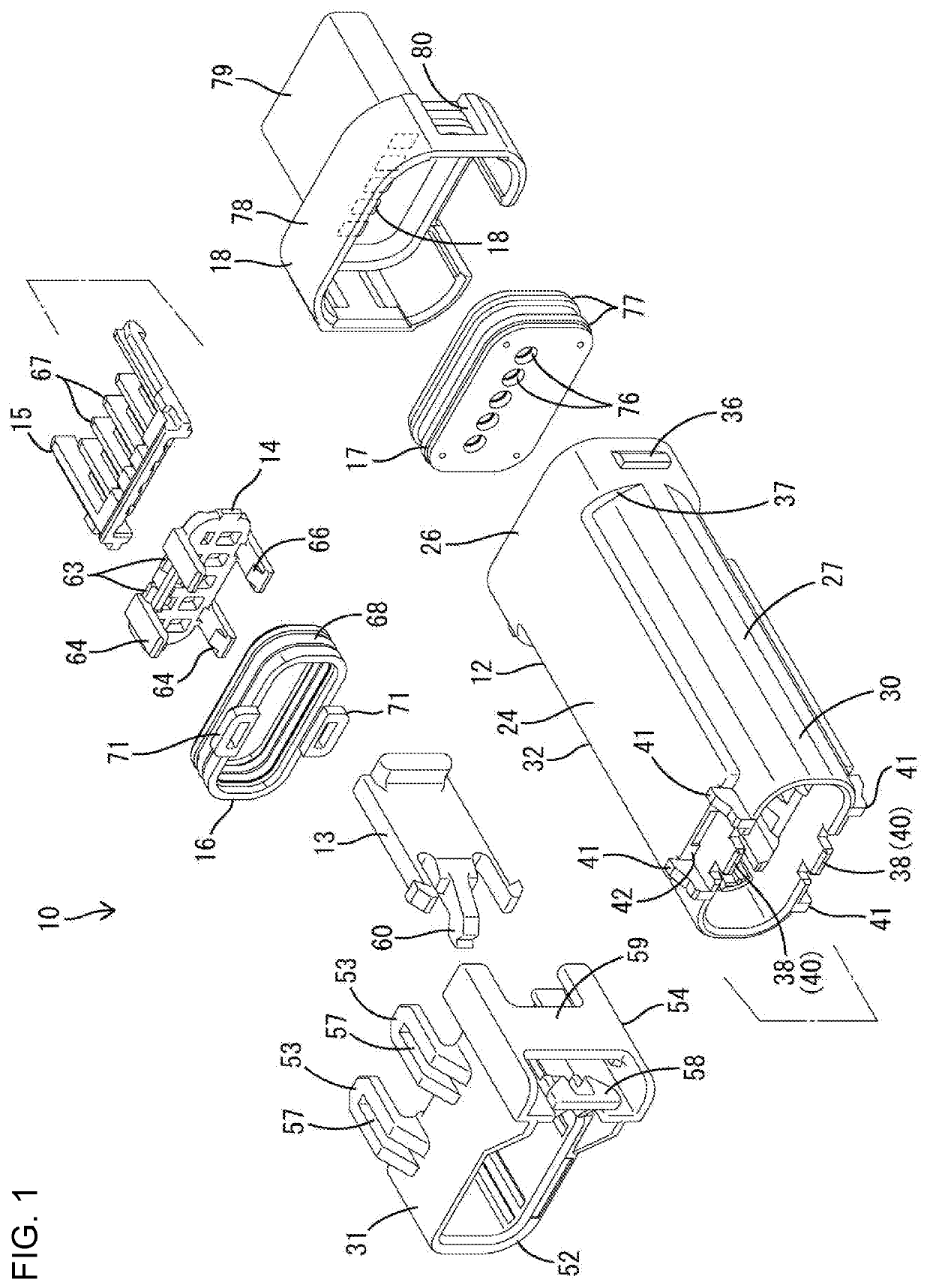
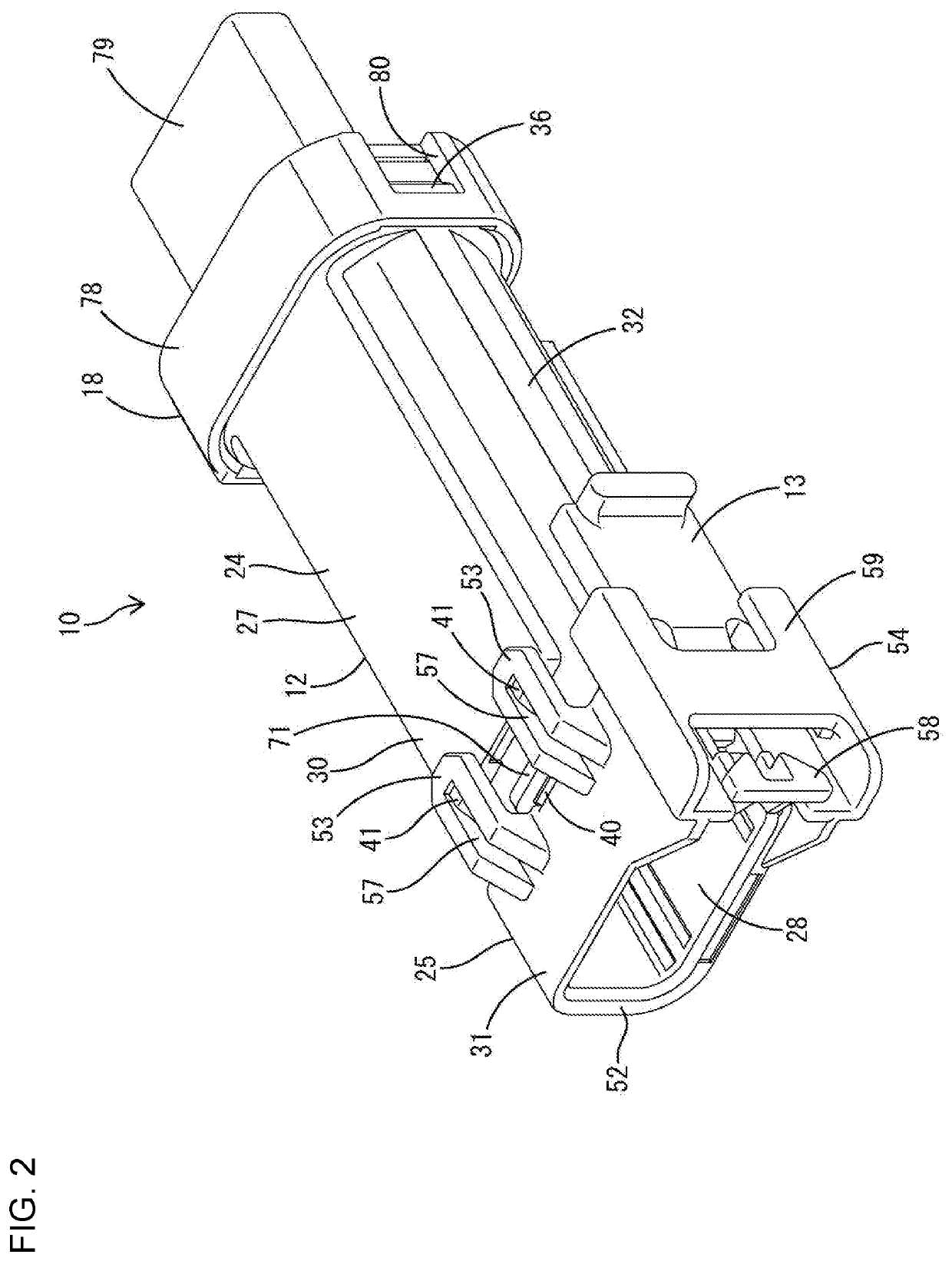
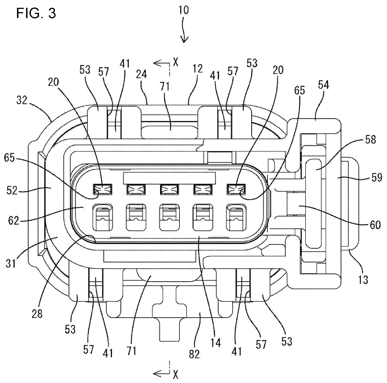
[0032]An embodiment of the invention is described with reference to FIGS. 1 to 16. As shown in FIGS. 15 and 16, this embodiment is composed of a male connector 10 and a female connector 100 connectable to and separable from each other. As shown in FIGS. 1 and 4, the male connector 10 includes male terminal fittings 11, a male housing 12, a detecting member 13, a moving plate 14, a retainer 15, a sealing member 16, a sealing plug 17 and a rear holder 18. As shown in FIGS. 10, 11 and 15, the female connector 100 includes female terminal fittings 101, a female housing 102, a retainer 104, a sealing plug 103 and a rear holder 105. The retainer 15, the sealing plug 17 and the rear holder 18 of the male connector 10 are different in shape from the retainer 104, the sealing plug 103 and the rear holder 105 of the female connector 100. However, the same terms are given since these components exhibit substantially the same functions. The same terms are given to other structures if substantia...


PUM


Abstract

A moving plate (14) is movable in a fitting space (28) of a receptacle (25) between a protecting position and a retracted position. A sealing member (16) is closer to an opening than the moving plate (14) and closely contacts the inner surface of the receptacle (25). The moving plate (14) has arms (64) including inward projecting locking projections (66). A female housing (102) fits into the fitting space (28) of the receptacle (25) and includes a sealing surface (116) and recesses (112) on an outer surface. The sealing surface (116) contacts the inner surface of the sealing member (16) during connection to a male connector (10). The recesses (112) are recessed on a more forward side than the sealing surface (116) in a fitting direction into the fitting space (28), and locking projections (66) are locked to side surfaces of the recesses during separation from the male connector.

Description

BACKGROUNDField of the Invention[0001]The invention relates to a connector.Related Art[0002]Japanese Unexamined Patent Publication No. 2003-68401 discloses a male connector with male terminal fittings including tabs, a receptacle arranged such that the tabs project therein and a moving plate arranged movably in the receptacle to position and protect tips of the tabs at an initial position (protecting position).[0003]A female connector is provided to connect with the male connector and includes a female connector housing having a body that can fit into the moving plate. An annular sealing member is fit on the outer periphery of the body such that an outer surface of the sealing member closely contacts the inner surface of the receptacle, and an inner surface of the sealing member closely contacts the outer surface of the body. Thus, the male and female connectors are connected in a liquid-tight manner via the sealing member.[0004]The moving plate can return to the initial position wh...

Claims


Application Information

Patent Timeline
IPC IPC(8): H01R13/436H01R13/52H01R13/64H01R13/506H01R13/629
CPCH01R13/5202H01R13/506H01R13/629H01R13/4362H01R13/64H01R13/502H01R13/5221H01R13/6272H01R13/641H01R24/00H01R13/4367H01R13/4538H01R13/5219
Inventor MAMIYA, YUMAKIDA, SHINJIROSAITO, SHO
Owner SUMITOMO WIRING SYST LTD
Learn More