Method and apparatus for receiving positioning signals based on pseudorange corrections

a positioning signal and pseudorange correction technology, applied in satellite radio beaconing, measurement devices, instruments, etc., can solve the problems of inaccurate positioning calculation, receivers may not have access to redundant satellites, and high risk of producing inaccurate positioning fixes

Inactive Publication Date: 2013-01-31
SAMSUNG ELECTRONICS CO LTD
View PDF6 Cites 28 Cited by
  • Summary
  • Abstract
  • Description
  • Claims
  • Application Information

AI Technical Summary

Problems solved by technology

An error in a pseudorange measurement can lead to the position being incorrectly calculated.
However, in many situations, for example in urban areas, the receiver may not have access to redundant satellites.
The alternative is to use the small number of satellites that are available, which carries a high risk of producing an inaccurate position fix.

Method used


Image

  • Method and apparatus for receiving positioning signals based on pseudorange corrections
  • Method and apparatus for receiving positioning signals based on pseudorange corrections
  • Method and apparatus for receiving positioning signals based on pseudorange corrections

Examples


Embodiment Construction

[0018]Hereinafter, embodiments of the present invention will be described with reference to the accompanying drawings. In the following description, the same elements will be designated by the same reference numerals although they are shown in different drawings. In the drawings, the thickness of lines and sizes of components may be exaggerated for the clarity and convenience of description. The terminologies used hereinbelow are those defined in consideration of functions in the present invention, and different terminologies may be used in accordance with an intention of a user or an operator or a practice. Further, a detailed description of known functions and configurations incorporated herein will be omitted for the sake of clarity and conciseness.

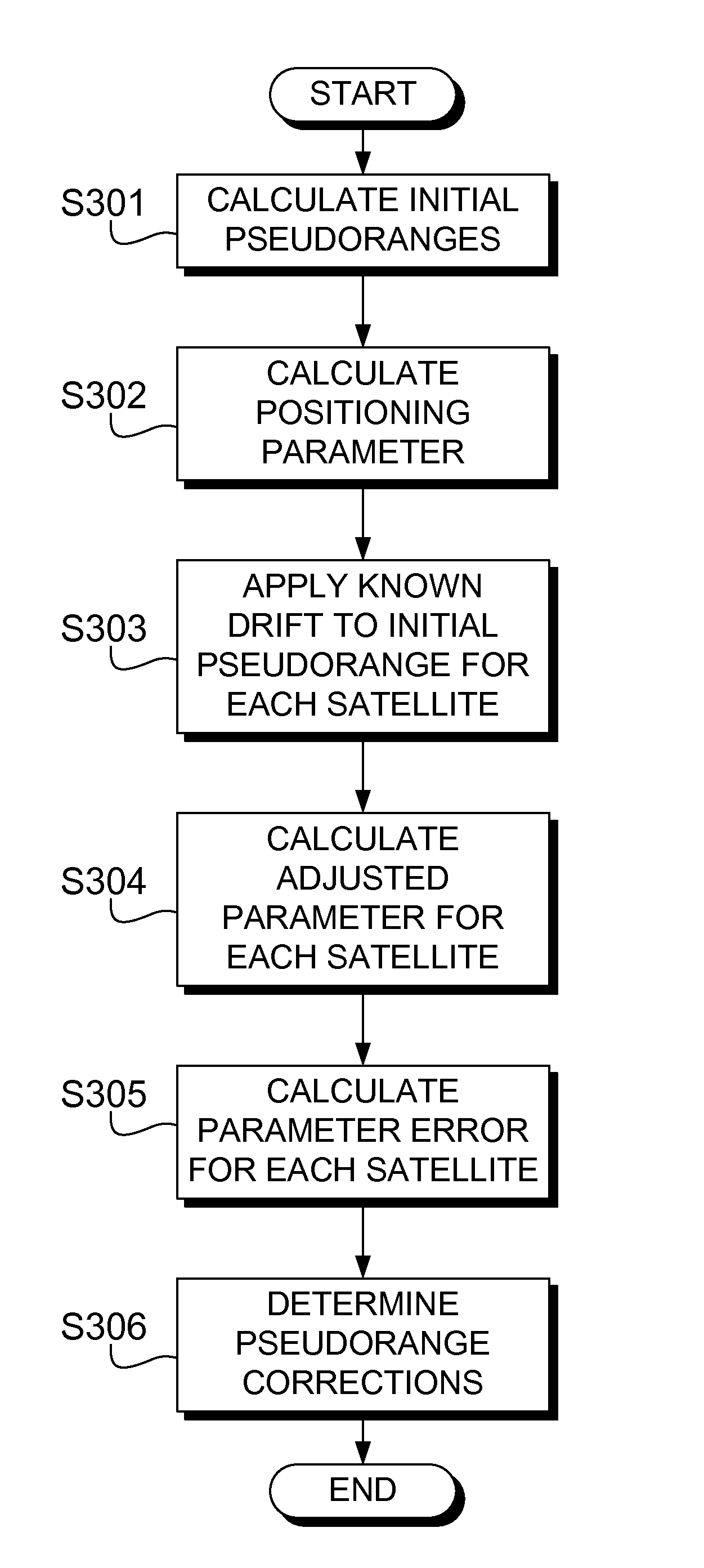
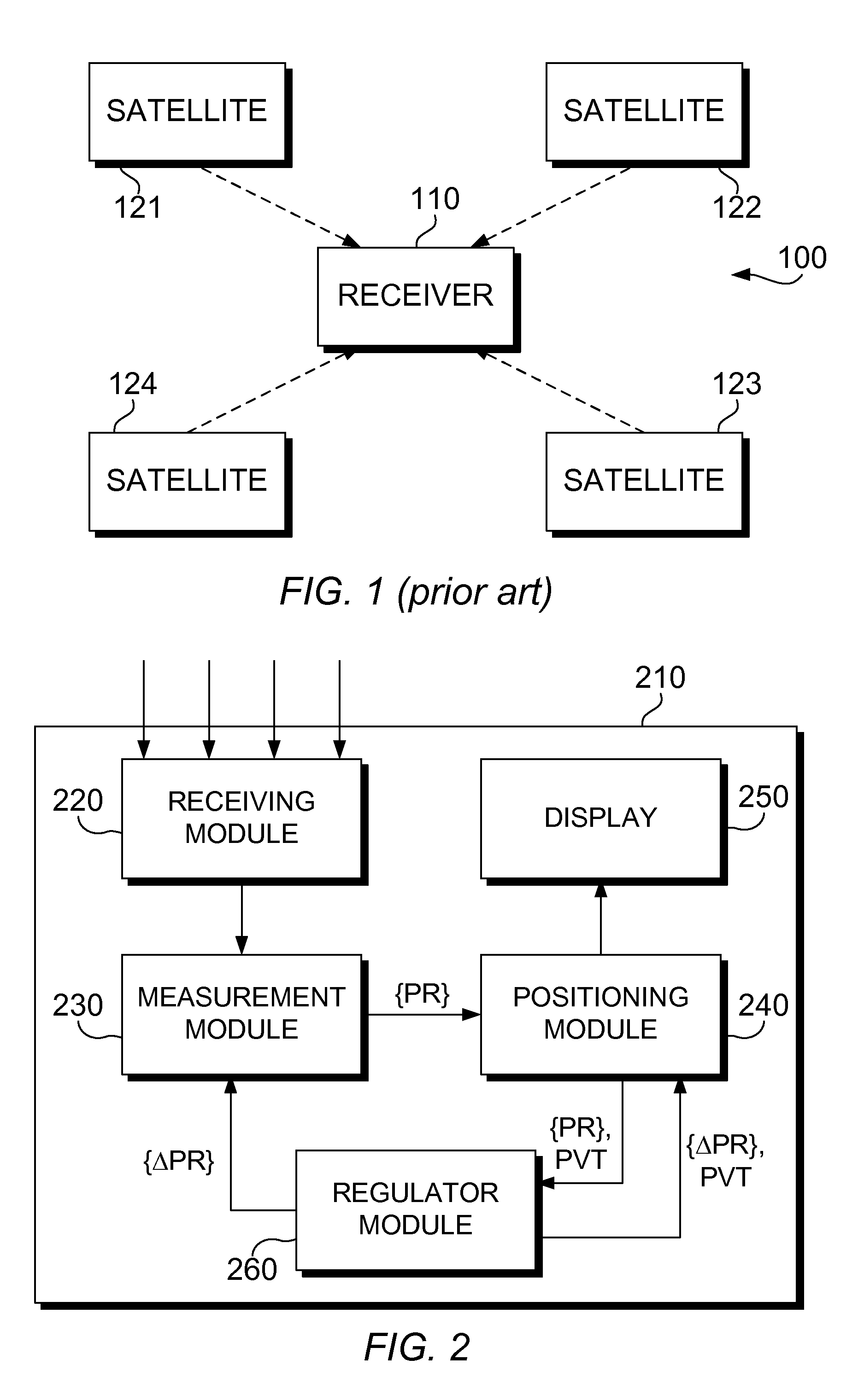
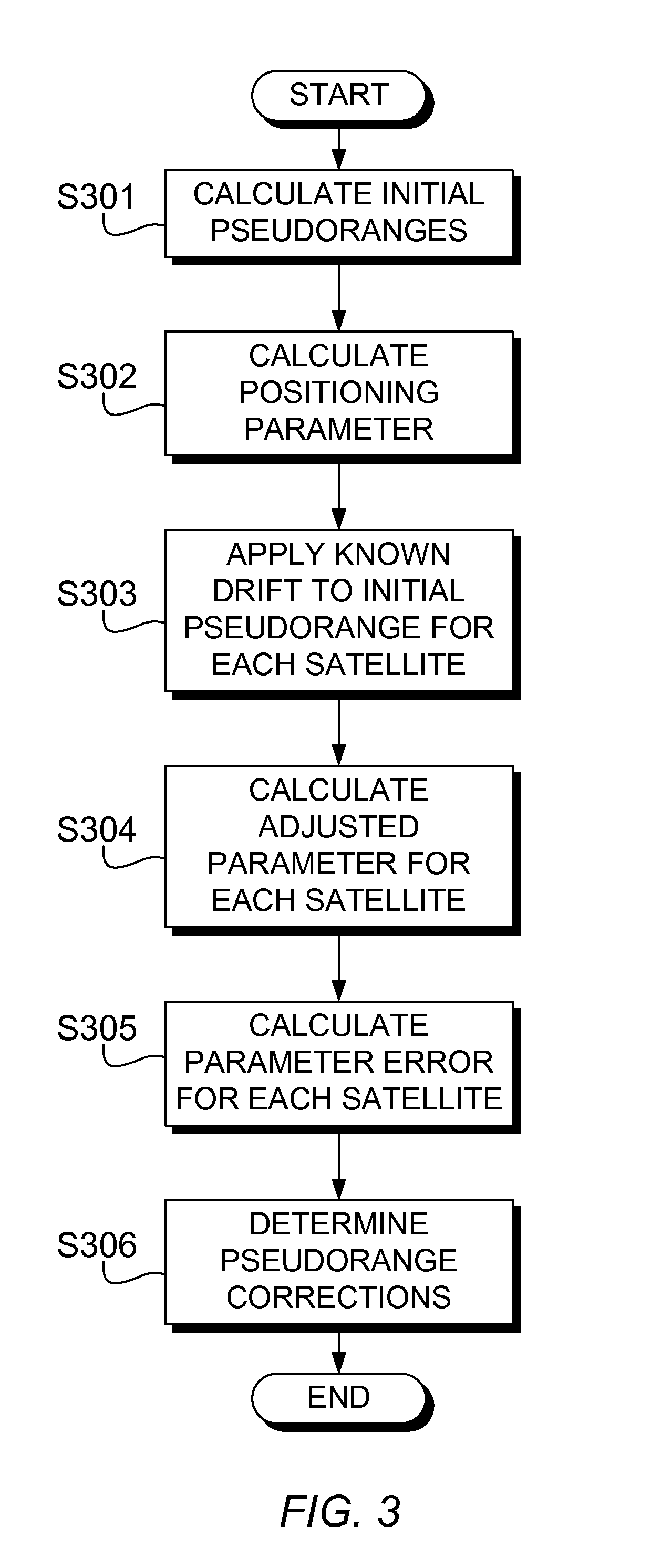
[0019]FIG. 2 illustrates a receiver for use in a satellite navigation system, according to an embodiment of the present invention. The receiver 210 comprises a receiving module 220 for receiving positioning signals from a plurality of ...


PUM


Abstract

A receiver for receiving positioning signals from a plurality of sources obtains a pseudorange correction for each source by obtaining an initial pseudorange to each source, an initial value of a positioning parameter based on the initial pseudoranges, a difference between the initial value of the positioning parameter and a reference value of the positioning parameter, a parameter error for each one of the sources, and the pseudorange correction for each source based on the difference between the initial and the reference values of the positioning parameter, the parameter error for the source and the value.

Description

PRIORITY[0001]This application claims priority under 35 U.S.C. §119(a) to an application filed in the Great Britain Intellectual Property Office on Jul. 28, 2011 and assigned Serial No. 1113014.3, the contents of which are incorporated herein by reference.BACKGROUND OF THE INVENTION[0002]1. Field of the Invention[0003]The present invention relates generally to receiving positioning signals, and more particularly, to calculating pseudoranges to a plurality of sources from which positioning signals are received, and determining a correction to be applied to each pseudorange.[0004]2. Description of the Related Art[0005]FIG. 1 illustrates a conventional Global Navigation Satellite System (GNSS). The system 100 includes a plurality of satellites 121, 122, 123, 124 and a receiver 110 which receives positioning signals from the plurality of satellites. In FIG. 1, four satellites are shown, but more satellites may be provided for improved accuracy / redundancy. The receiver 110 calculates its...

Claims


Application Information

Patent Timeline
Patent Type & Authority Applications(United States)
IPC IPC(8): G01S19/42
CPCG01S19/40G01S19/23G01S19/07
Inventor HADEF, MAHMOUD
Owner SAMSUNG ELECTRONICS CO LTD
Why Eureka
Try Eureka